
Eyeglass lens processing apparatus

a technology for processing apparatuses and lenses, applied in the direction of other manufacturing equipment/tools, grinding machine components, manufacturing tools, etc., can solve the problem of complicated apparatus configuration

Inactive Publication Date: 2006-10-26
NIDEK CO LTD
View PDF0 Cites 34 Cited by
  • Summary
  • Abstract
  • Description
  • Claims
  • Application Information

AI Technical Summary

Benefits of technology

[0021] wherein the control unit controls the end mill tilting unit and the end mill moving unit to perform the beveling process on the front surface side of the lens using one of the end mills and to perform the beveling process on the rear surface side of the lens using t...

Problems solved by technology

Since the drilling mechanism is disposed independently of the periphery processing mechanism, the configuration of the apparatus is complicated.

Method used


Image

  • Eyeglass lens processing apparatus
  • Eyeglass lens processing apparatus
  • Eyeglass lens processing apparatus

Examples


Embodiment Construction

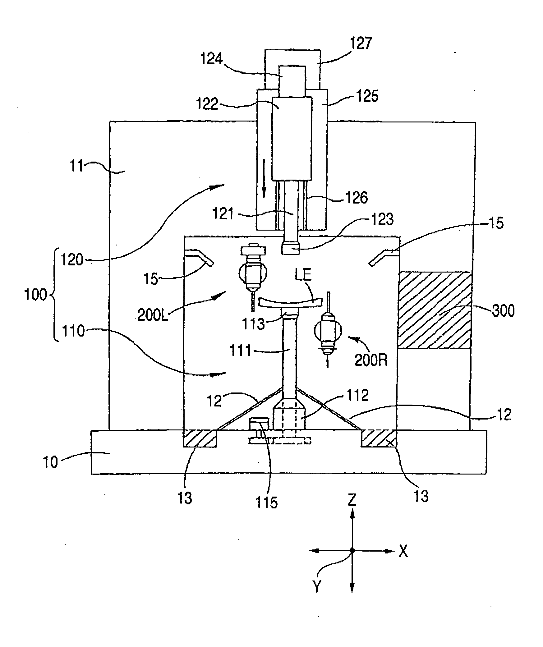
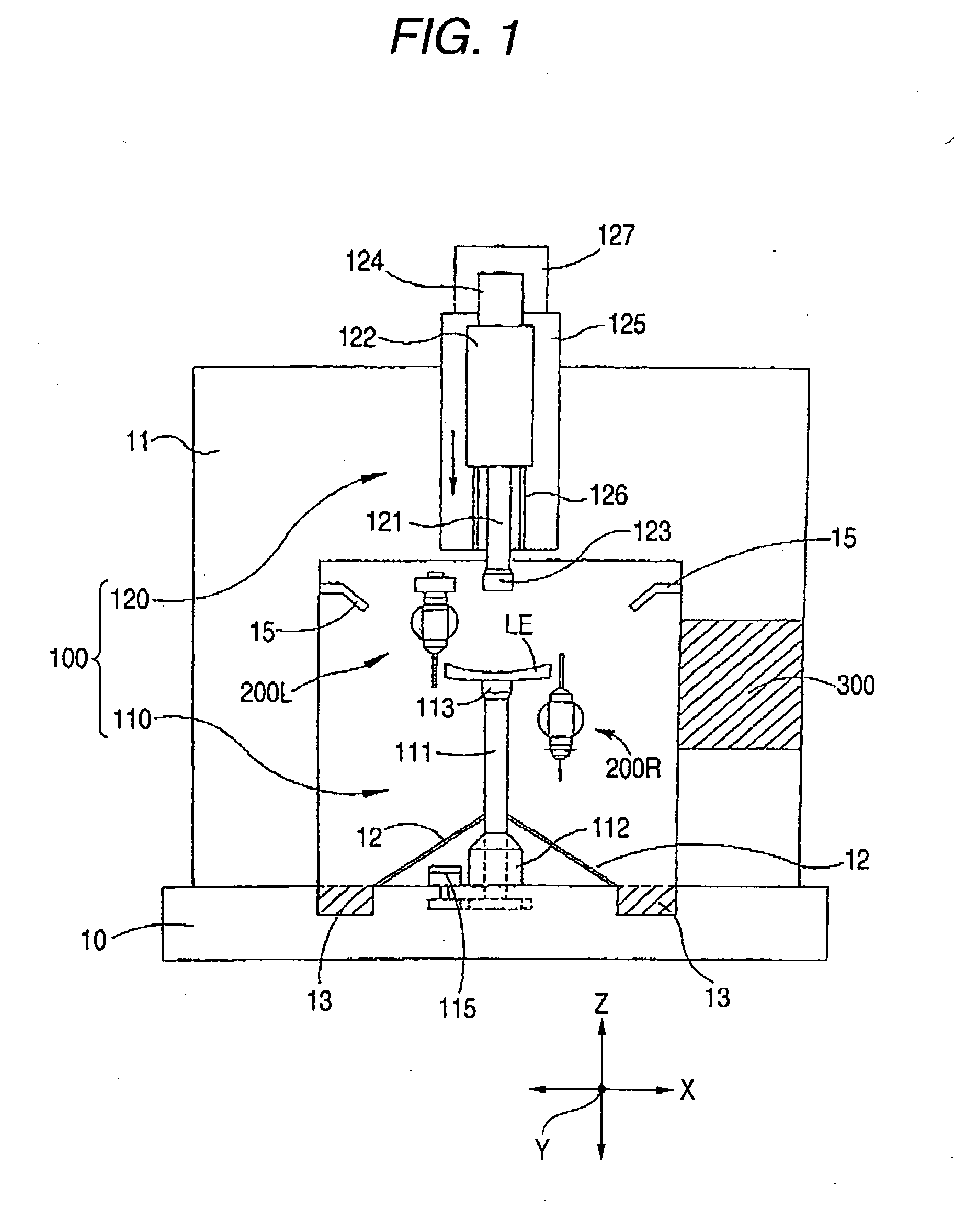
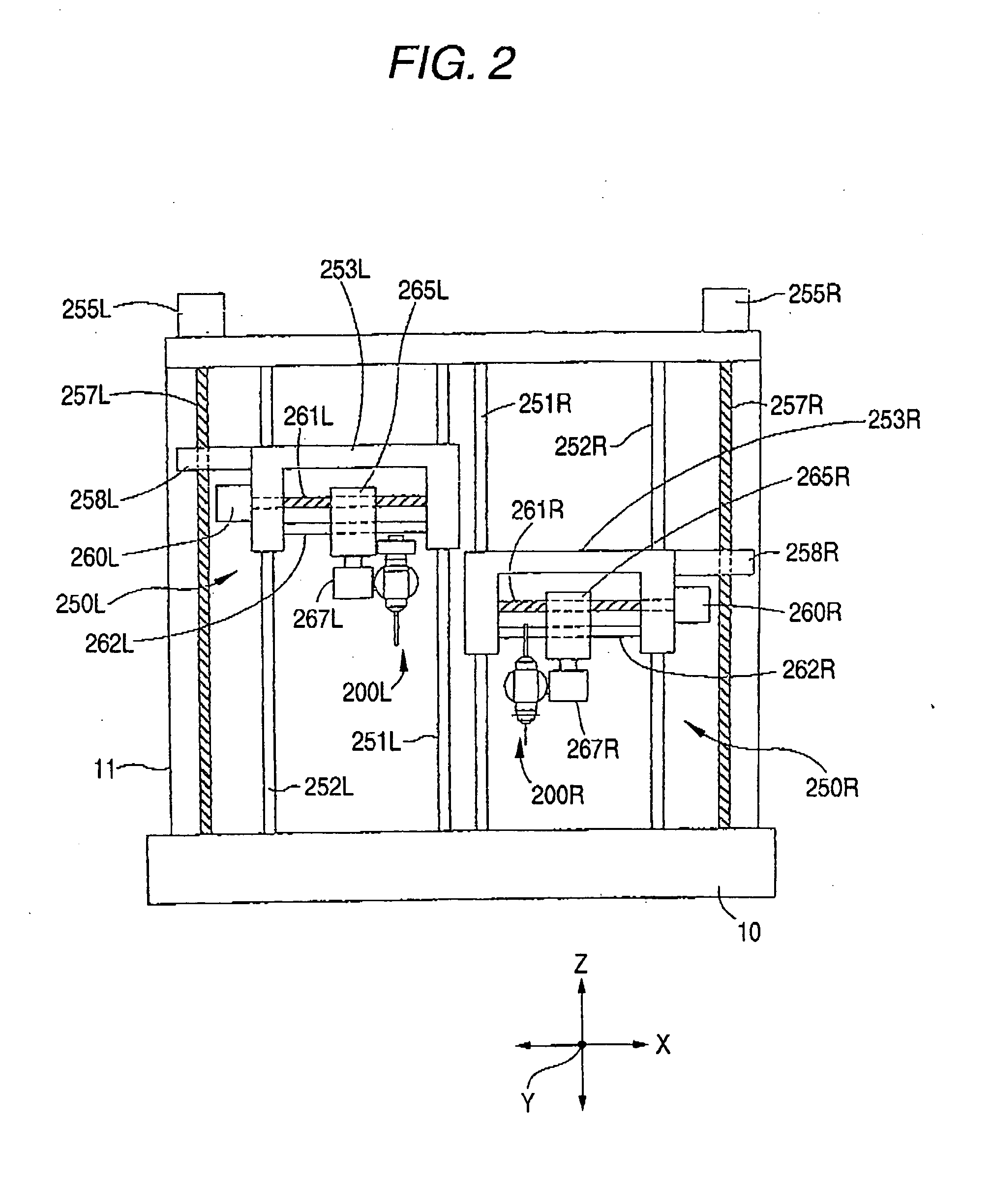
[0044] Hereinafter, exemplary embodiments of the present invention will be described in detail with reference to the drawings. FIG. 1 is a diagram schematically illustrating a configuration of a lens processing section of an eyeglass lens processing apparatus according to an embodiment of the invention. A sub base 11 is disposed on a main base 10 and a lens holding unit 100 is disposed in the bases 10 and 11. The holding unit 100 includes a lower lens holding unit 110 and an upper lens holding unit 120. A lens LE to be processed is chucked (interposed) between a lens chuck shaft (lens rotating shaft) 111 of the holding unit 110 and a lens chuck shaft (lens rotating shaft) 121 of the holding unit 120. The chuck shaft 111 is rotatably supported by a holder 112 fixed to the main base 10 and is rotated by a pulse motor 115 fixed to the main base 10. The chuck shaft 121 is rotatably supported by a holder 122 and is rotated by a pulse motor 124 fixed to the holder 122. When the lens LE is...


PUM

PropertyMeasurementUnit
Angleaaaaaaaaaa
Refractionaaaaaaaaaa

Abstract

An eyeglass lens processing apparatus for processing a periphery of an eyeglass lens, the apparatus includes: a lens chuck shaft that holds and rotates the lens; an end mill that processes the periphery of the lens; an end mill tilting unit that varies a tilt of the end mill with respect to the lens chuck shaft; an end mill moving unit that relatively moves the end mill with respect to the lens held by the lens chuck shaft; a target lens shape input unit that inputs an target lens shape; a lens measuring unit that detects a position of a processing edge of the lens based on the input target lens shape; a memory that stores a beveling shape including a beveling tilt angle on a front surface side of the lens and a beveling tilt angle on a rear surface side of the lens; and a control unit that controls the end mill tilting unit and the end mill moving unit to perform a roughing process on the lens using the end mill based on the input target lens shape and to perform a beveling process on the roughing-processed lens using the end mill based on the detected position of the processing edge and the stored beveling shape.

Description

BACKGROUND OF THE INVENTION [0001] 1. Technical Field [0002] The present invention relates to an eyeglass lens processing apparatus for processing a,periphery of an eyeglass lens. [0003] 2. Related Art [0004] Eyeglass lens processing apparatuses for processing a periphery of an eyeglass lens so as to correspond to the shape of a rim of a pair of eyeglasses mainly employ grindstones (abrasive wheels). As examples of the grindstones, there are a roughing grindstone, a plane-finishing grindstone, a beveling (bevel-finishing) grindstone, a chamfering grindstone, a polishing grindstone and the like. There has been suggested an eyeglass lens processing apparatus having a drilling mechanism for forming a hole for fitting a rimless frame (that is, two-point frame) to a refractive surface of the lens, in addition to a mechanism for processing (grinding) the periphery of the lens using the grindstones. [0005] However, it is necessary to supply processing water (grinding water) for the process...

Claims


Application Information

Patent Timeline
IPC IPC(8): B24B51/00B24B49/00B24B1/00B23C3/12B24B9/14
CPCB23C3/12B23C2215/40B24B9/14B24B49/00B28D1/143Y10T409/309576Y10T408/56245Y10T29/53865Y10T29/5114Y10T29/50Y10T409/307728
Inventor NATSUME, KATSUHIROSUGIURA, YOICHI
Owner NIDEK CO LTD
Learn More