Ultrasonic probe and ultrasonographic device

a technology of ultrasonic probes and ultrasonographic devices, applied in the field of ultrasonic probes, can solve the problems of large error, increased size of ultrasonic diagnostic equipment, and increased workability and cost, and achieve the effect of not affecting the productivity of treatmen

Inactive Publication Date: 2006-10-26
PANASONIC CORP
View PDF14 Cites 14 Cited by
  • Summary
  • Abstract
  • Description
  • Claims
  • Application Information

AI Technical Summary

Benefits of technology

[0016] The present invention intends to solve the above-mentioned conventional problems so as to provide an excellent ultrasonic diagnostic apparatus that can form a three-dimensional image in a more spatially-correct positi...

Problems solved by technology

However, this kind of ultrasonic probe requires to have a power supply, a switch and the like for the correction and needs a discontinuance of the operation thereof, which leads to an increase in the size of an ultrasonic diagnostic apparatus and causes a problem in workability and cost.
Therefore, according to the ultrasonic probe to be used, the formed three-dimensional image is distorted, is displaced, flickers due to the reciprocation of its swinging or the like, which may result in problems such as penetrating in a direction deviat...

Method used


Image

  • Ultrasonic probe and ultrasonographic device
  • Ultrasonic probe and ultrasonographic device
  • Ultrasonic probe and ultrasonographic device

Examples


embodiment 1

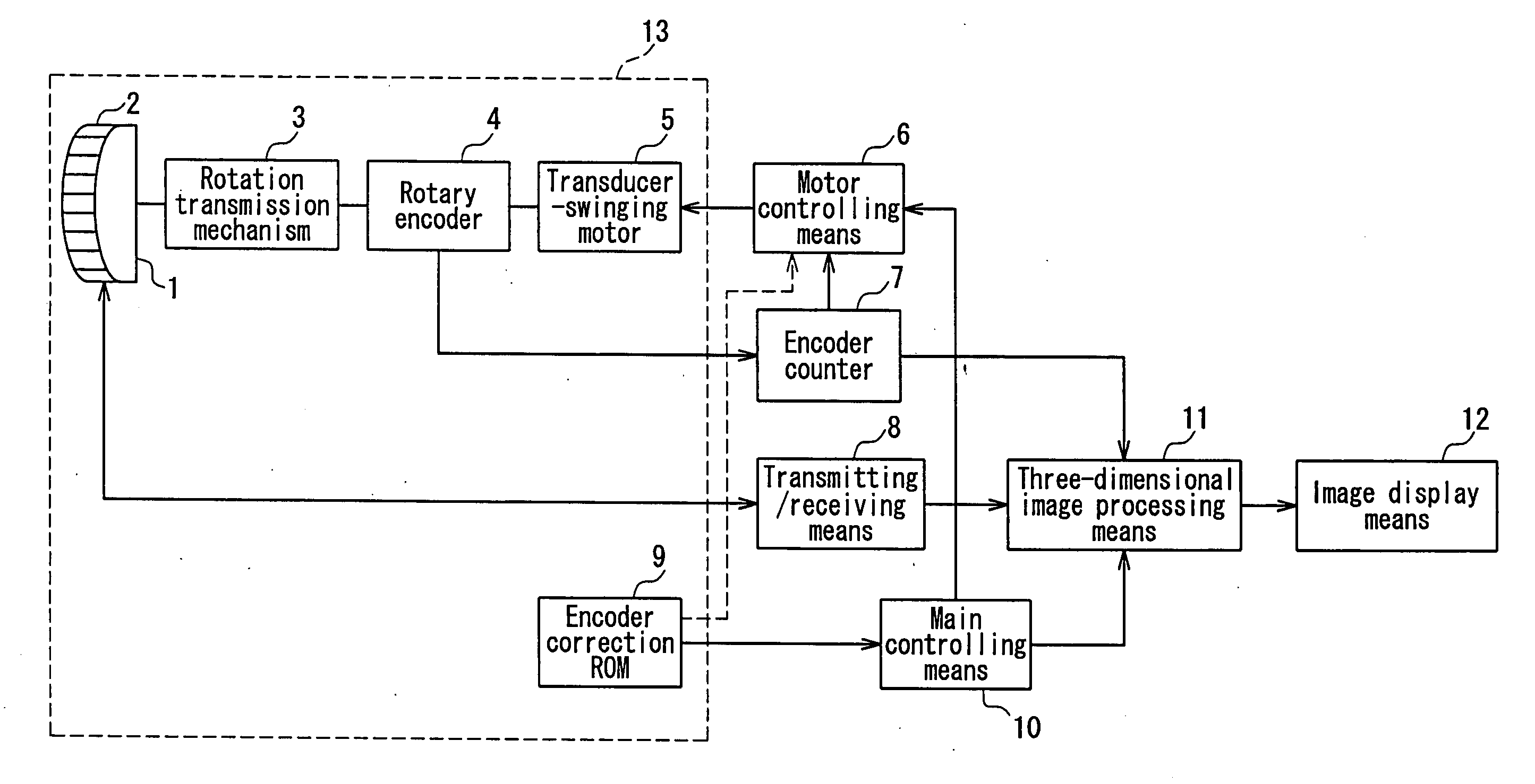
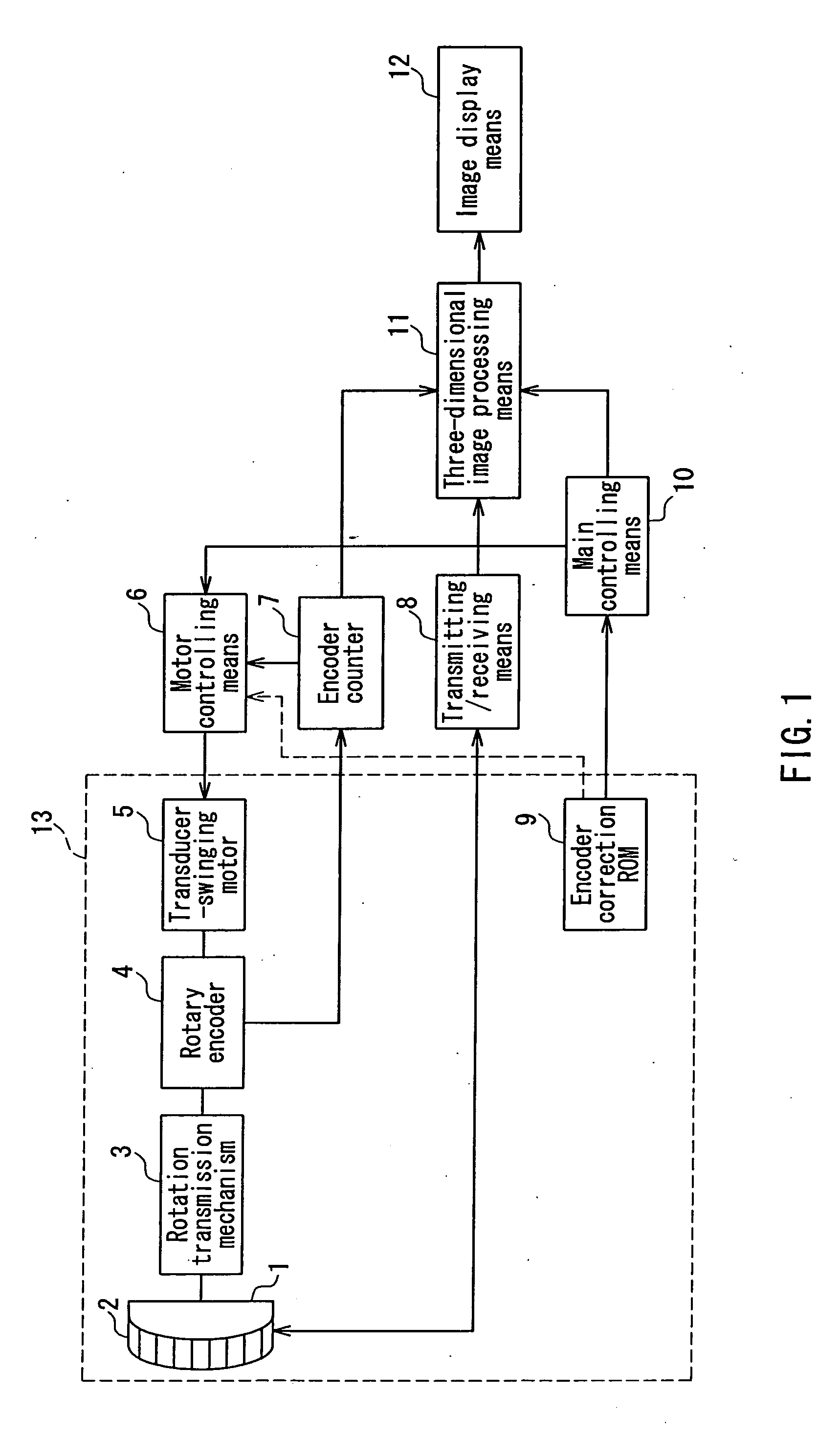
[0036]FIG. 1 is a block diagram showing an example of a configuration of the ultrasonic diagnostic apparatus according to Embodiment 1 of the present invention. The ultrasonic diagnostic apparatus shown in FIG. 1 will be applied also in the respective embodiments described below.

[0037] In FIG. 1, the ultrasonic diagnostic apparatus according to the present embodiment includes an ultrasonic transducer 1 with a plurality of transducer elements 2 arranged in array, the transducer element 2 transmitting an ultrasonic beam into a living body and converting an ultrasonic echo from a tissue in the living body into an electric signal. Each of the transducer elements 2 is excited by a transmission pulse provided by a transmitting / receiving means 8. The transmitting / receiving means 8 is controlled to provide the transmission pulses with different phases to a part of or all of the transducer elements 2 arranged in the ultrasonic transducer 1, so that the transmission pulse is focused at a pre...

embodiment 2

[0051] Next, Embodiment 2 of the present invention will be described with reference to FIG. 1 as well as Embodiment 1.

[0052] Generally, swing scanning mostly is performed as reciprocating scanning. This method is intended for forming a three-dimensional image at more real time. Also in this case, even when count values provided by the encoder counter 7 on a forward path of the swing scanning and on its return path are equal, real swing scanning angles thereof are often different, which is a problem caused by a mechanical scanning method, in addition to the above-mentioned problem.

[0053] This is caused mostly by the rotation transmission mechanism 3 that connects the rotation axis of the transducer-swinging motor 5 and the ultrasonic transducer 1. For example, in a rotation transmission mechanism using a gear, rotation angles of a passive gear with respect to an angle of a rotation axis of a motor in a forward rotation of the gear and in a reverse rotation thereof are different, du...

embodiment 3

[0056] Next, as Embodiment 3 of the present invention, an ultrasonic diagnostic apparatus that can form a more precise three-dimensional image by the ultrasonic probe 13 including the above-mentioned encoder correction ROM 9 and the like will be described with reference to FIGS. 2 to 6.

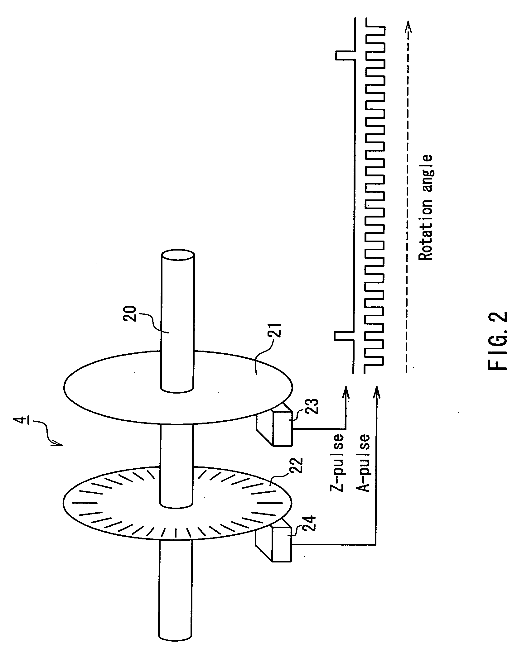
[0057] In the encoder correction ROM 9 of the ultrasonic diagnostic apparatus according to the present embodiment, a correction value 31 as shown in FIG. 3 is stored in advance. In FIG. 3, a straight line 30 shows a case where the swing scanning angle of the ultrasonic transducer 1 with respect to the count value of the encoder counter 7 is ideal, and where the encoder counter 7 is an up-counter, using the rotary encoder 4 that generates N number of A-pulses during one rotation of the rotation axis of the transducer-swinging motor 5 and a Z-pulse when the angle of the rotation axis is 0°. In addition, the present embodiment exemplifies the case where the angle of the rotation axis coincides with an a...


PUM


Abstract

An excellent ultrasonic diagnostic apparatus is provided that can form a three-dimensional image in a more spatially-correct position regardless of an ultrasonic probe to be used, without leading to deterioration of the productivity of the treatment. An ultrasonic probe includes an ultrasonic transducer, a rotation transmission mechanism, a rotary encoder, a transducer-swinging motor and an encoder correction ROM. In the encoder correction ROM, an actual swing scanning angle of the ultrasonic transducer with respect to each count value that is obtained by counting pulses from the rotary encoder is stored in advance. A three-dimensional image processing means forms a three-dimensional image of a principal cross-section scanning plane in a direction at the actual swing scanning angle, while correcting an encoder count value from an encoder counter according to contents of the encoder correction ROM that are read out by a main controlling means.

Description

TECHNICAL FIELD [0001] The present invention relates to an ultrasonic probe that is directed to obtaining three-dimensional echo data by receiving an ultrasonic echo that is obtained by the reflection of an ultrasonic beam transmitted with respect to a tissue in a living body or the like, and relates to an ultrasonic diagnostic apparatus in which the ultrasonic probe is used. BACKGROUND ART [0002] Conventionally, as an ultrasonic probe for obtaining three-dimensional data, which is used in an ultrasonic diagnostic apparatus intended to display the condition of a tissue in a living body three-dimensionally, an ultrasonic probe including an ultrasonic transducer for scanning an ultrasonic beam, which is configured so as to swing mechanically the ultrasonic transducer to perform swing scanning in a direction that crosses the beam scanning direction, is known (see, for example, JP 3(1991)-184532 A). By performing ultrasonic beam scanning (hereinafter, called principal cross-section scan...

Claims


Application Information

Patent Timeline
IPC IPC(8): A61B8/00
CPCA61B8/483A61B8/00A61B8/4461
Inventor AKIYAMA, HISASHIFUJII, KIYOSHI
Owner PANASONIC CORP
Why Eureka
Try Eureka