Polyaxial bone screw assembly with fixed retaining structure

a technology retaining structures, applied in the field of polyaxial bone screws, can solve the problems of unsatisfactory angular positioning, difficult or impossible to do, and difficult to rigidly fix to each other and bone, so as to prevent unintentional disassembly, reduce the number of components, and secure the effect of each other and bon

Inactive Publication Date: 2006-10-26
JACKSON
View PDF100 Cites 217 Cited by
  • Summary
  • Abstract
  • Description
  • Claims
  • Application Information

AI Technical Summary

Problems solved by technology

This is sometimes very difficult or impossible to do.
Consequently, heavy, bulky implants are undesirable and lighter implants with a relatively small profile both in height and width are more desirable.
However, a drawback to smaller, lighter implants is that they may be more difficult to rigidly fix to each other and into a desired angular position.
Lack of bulk may also mean lack of strength, resulting in slippage under high loading.
A further drawback of smaller components is that they may be difficult to handle during surgery because of their small size or fail to provide adequate driving or gripping surfaces for tools used to drive the shank into bone or drive the closure top into the screw head.

Method used


Image

  • Polyaxial bone screw assembly with fixed retaining structure
  • Polyaxial bone screw assembly with fixed retaining structure
  • Polyaxial bone screw assembly with fixed retaining structure

Examples


Embodiment Construction

[0045] As required, detailed embodiments of the present invention are disclosed herein; however, it is to be understood that the disclosed embodiments are merely exemplary of the invention, which may be embodied in various forms. Therefore, specific structural and functional details disclosed herein are not to be interpreted as limiting, but merely as a basis for the claims and as a representative basis for teaching one skilled in the art to variously employ the present invention in virtually any appropriately detailed structure.

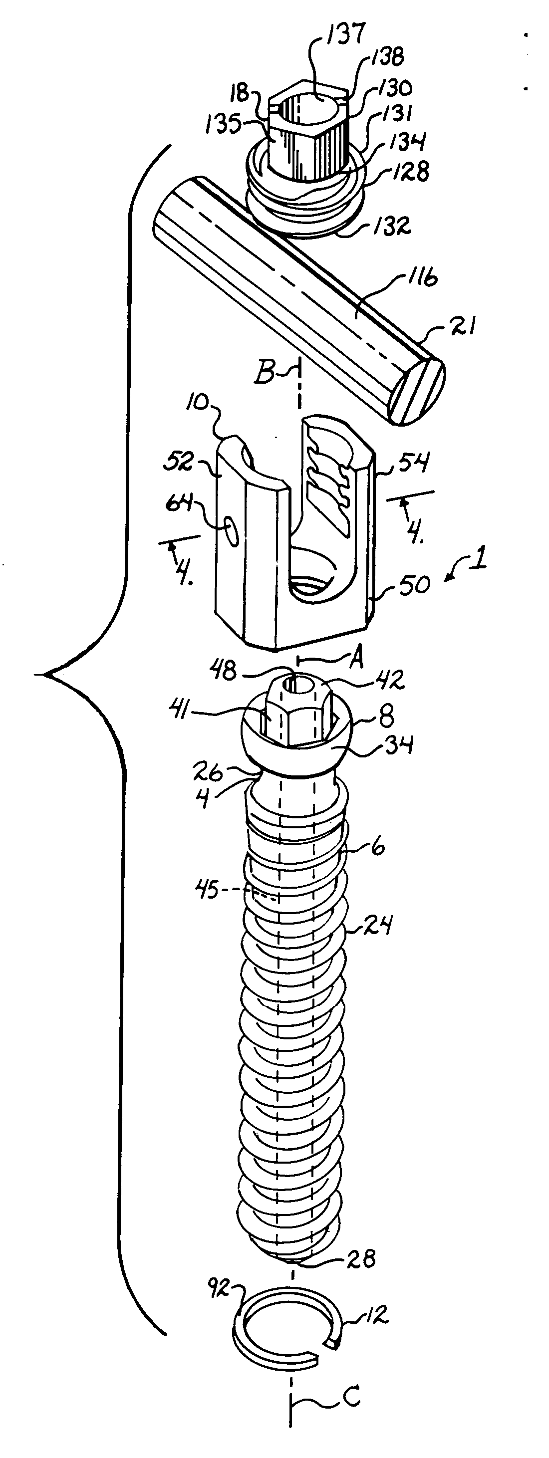
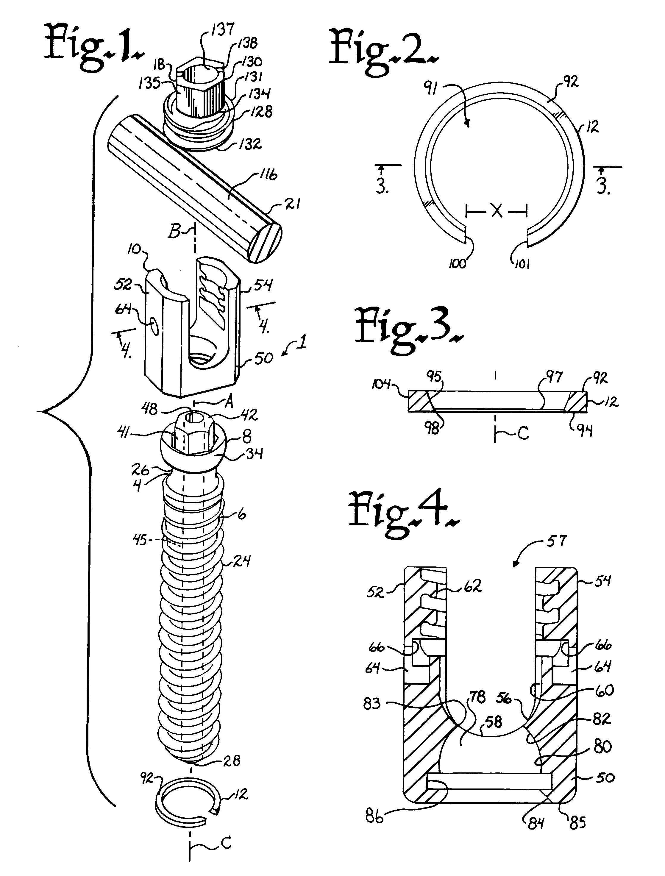
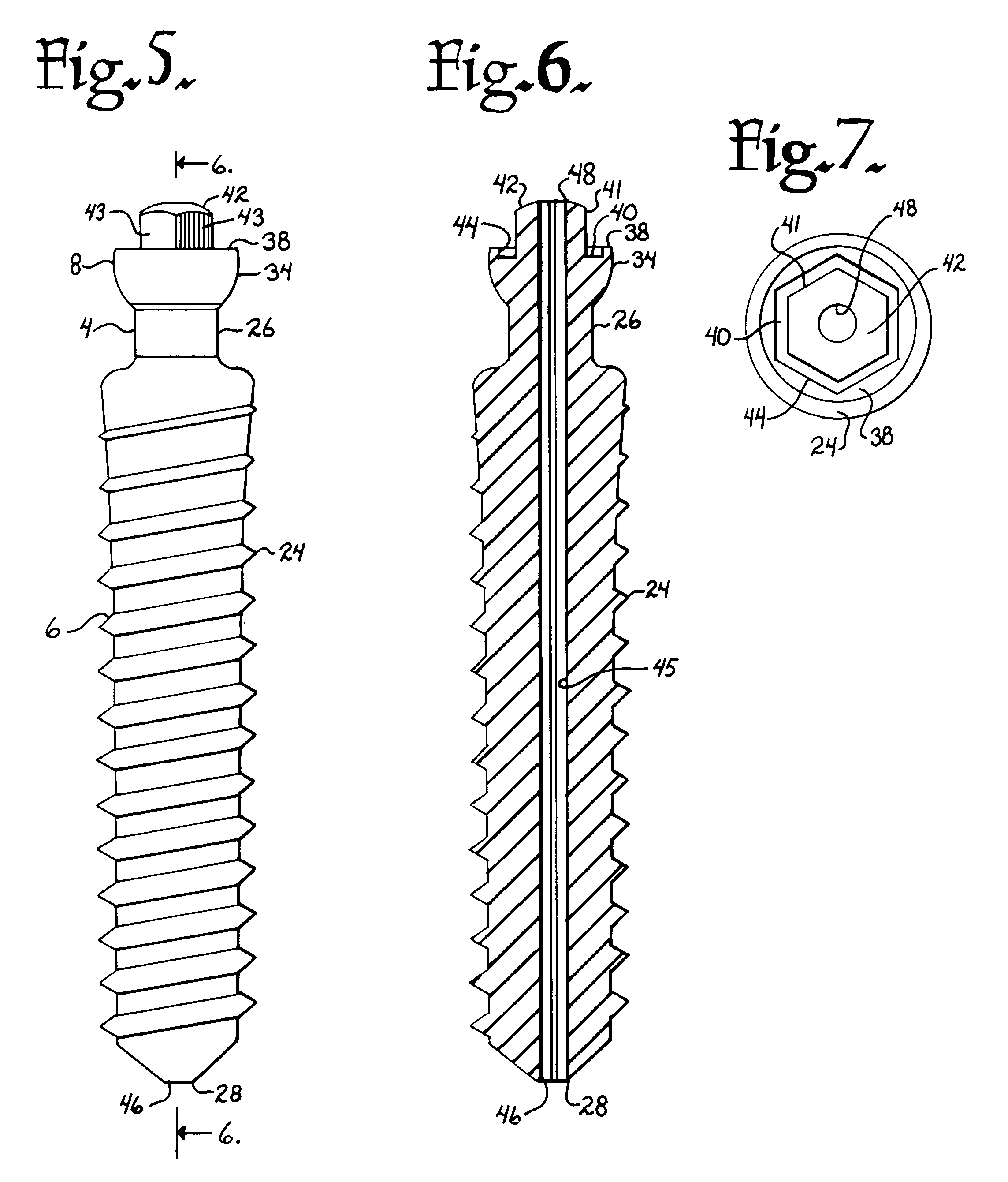
[0046] With reference to FIGS. 1-10, the reference numeral 1 generally represents a polyaxial bone screw assembly according to the present invention. The assembly 1 includes a shank 4 that further includes a body 6 integral with an upwardly extending upper portion or capture structure 8; a receiver 10; and an independent open retaining structure 12. The shank 4, the receiver 10 and the retaining structure 12 preferably are assembled prior to implantation of...


PUM


Abstract

A polyaxial bone screw assembly includes a threaded shank body having an integral upper portion receivable in a receiver and retained within the receiver by a retaining structure in the form of an open ring. The retaining structure is compressible, having an opening with two ends that may be pressed toward one another. The receiver has a U-shaped cradle defining a channel for receiving a spinal fixation rod. The receiver channel communicates with a cavity partially defined by an upper spherical surface and a substantially cylindrical surface communicating with a bottom opening of the receiver that allows for bottom loading the shank upper portion and the compressed retaining structure into the receiver, but prevents passage of the retaining structure out of the receiver once the retaining structure expands to an original form thereof and thus retains the shank upper portion within the cavity. The shank upper portion is designed to directly frictionally engage the spinal fixation rod when a closure structure operably urges the rod toward the upper portion, fixing the bone screw shank body in a selected angular orientation with respect to the receiver.

Description

CROSS REFERENCE TO RELATED APPLICATIONS [0001] This application claims the benefit of U.S. Provisional Application No. 60 / 699,092 filed Jul. 14, 2005. The present application is a continuation-in-part of U.S. patent application Ser. No. 10 / 818,554, filed Apr. 5, 2004 which was a continuation of U.S. patent application Ser. No. 10 / 464,633, filed Jun. 18, 2003, now U.S. Pat. No. 6,716,214 and a continuation-in-part of U.S. patent application Ser. No. 10 / 651,003, filed Aug. 28, 2003, now Patent No. ______BACKGROUND OF THE INVENTION [0002] The present invention is directed to polyaxial bone screws for use in bone surgery, particularly spinal surgery. Such screws have a rod receiver that can swivel about a shank of the bone screw, allowing the receiver to be positioned in any of a number of angular configurations relative to the shank. [0003] Many spinal surgery procedures require securing various implants to bone and especially to vertebrae along the spine. For example, elongate rods ar...

Claims


Application Information

Patent Timeline
Patent Type & Authority Applications(United States)
IPC IPC(8): A61F2/30
CPCA61B17/7011A61B17/7032A61B17/8605A61B17/863A61B2019/307A61B17/7037A61B2090/037A61B17/864
Inventor JACKSON, ROGER P.
Owner JACKSON
Why Eureka
Try Eureka