Subarray matching beamformer apparatus and method

a beamformer and subarray technology, applied in direction/deviation determination systems, instruments, using reradiation, etc., can solve problems such as difficult implementation of models that estimate array shape based on course maneuvers, distortion of towed arrays, and impaired target tracking and focus

a beamformer and subarray technology, applied in direction/deviation determination systems, instruments, using reradiation, etc., can solve problems such as difficult implementation of models that estimate array shape based on course maneuvers, distortion of towed arrays, and impaired target tracking and focus

US20060241914A1Inactive Publication Date: 2006-10-26LOCKHEED MARTIN CORP

Image

  • Subarray matching beamformer apparatus and method
  • Subarray matching beamformer apparatus and method
  • Subarray matching beamformer apparatus and method

Examples


Embodiment Construction

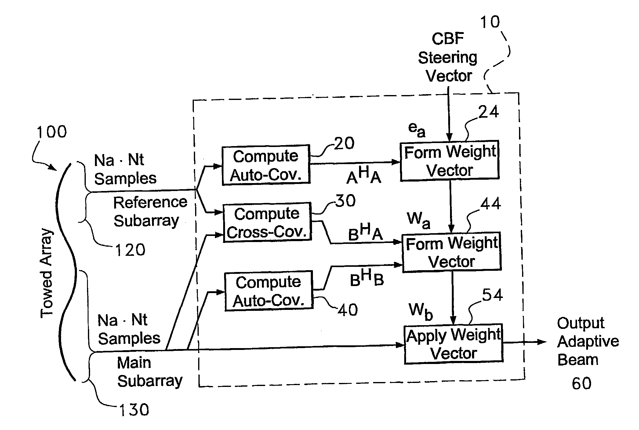
[0017] The method and system of the present invention allows for beamforming an array of unknown shape. To steer the array towards a particular direction, a processor first computes the standard adaptive weight vector across a subarray chosen small enough to assume negligible loss due to the distorted shape. Next, by utilizing the cross-covariance between this small subarray and the remaining elements of the array, the processor maps the short vector to a lengthened one which serves as an estimate of the steering weights for the main portion of the array. Note that this lengthened weight vector is obtained absent any information about the location of the array elements.

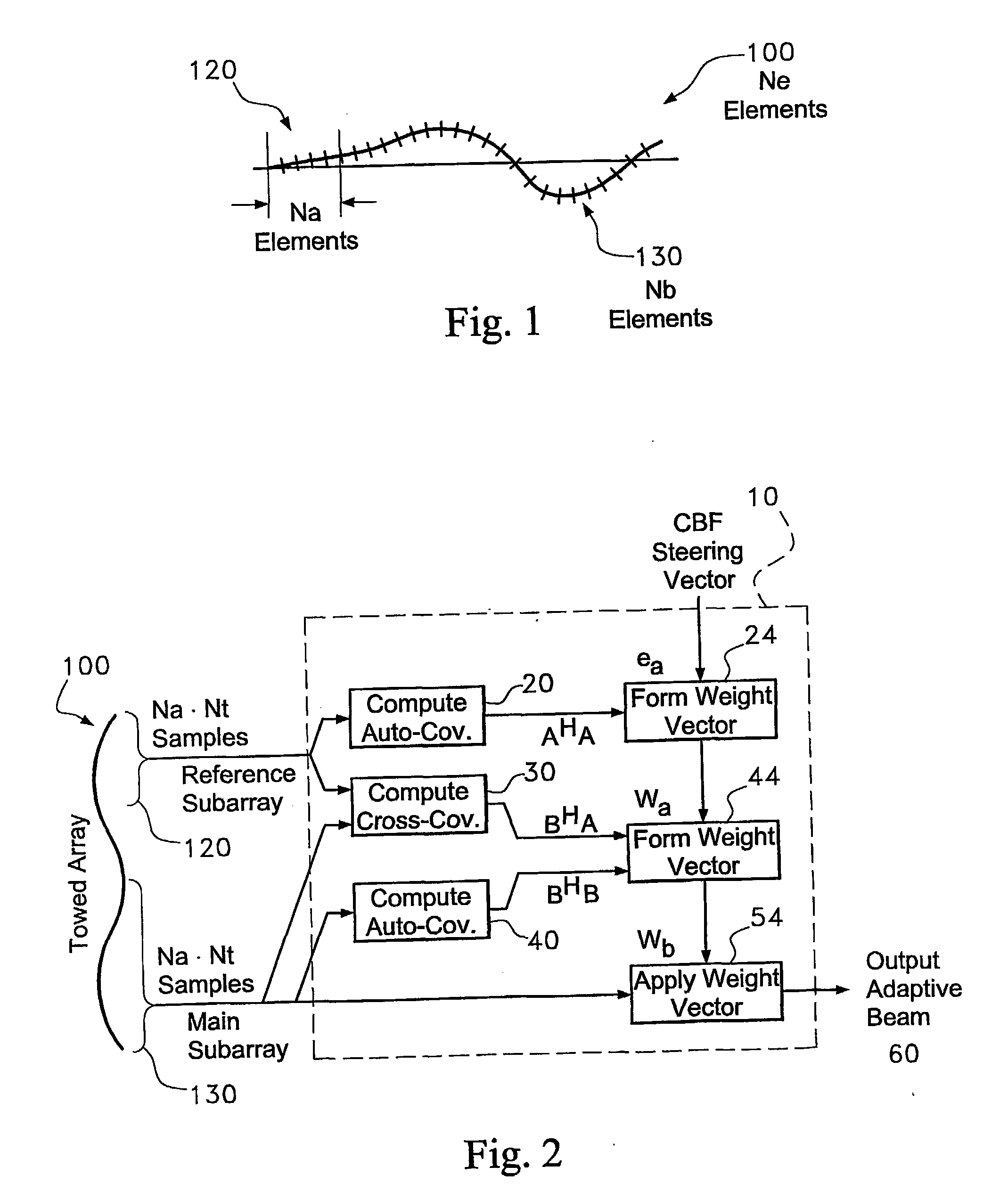
[0018] Referring now to the drawings, and in particular to FIGS. 1 and 2, wherein like reference numerals are used to indicate like parts, there is shown an apparatus 10 embodied in a sonar system for deriving adaptive weights for processing acoustic data received from an array 100 of hydrophones.

[0019] As shown in ...


PUM


Abstract

A method of beam forming an array (60), by computer processing a cross covariance (30), of the reference sub array seismic signal data signal (120), by having an unknown shape comprising receiving acoustic signals (120), via the aray (100), and computing the date (20) and segmenting the array into an initial segment of a known shape and at least a second segment (44), and beam forming the initial segment to provide a beam formed output (60), and using the beam formed output to obtain weights (24), for the second segment of the array.

Description

RELATED APPLICATION [0001] This application claims priority of U.S. Patent application 60 / 174,721, entitled SUBARRAY MATCHING BEAMFORMER (SMB) ALGORITHM, filed Jan. 6, 2000, the entire disclosure of which is incorporated by reference herein.STATEMENT OF GOVERNMENT INTEREST [0002] The invention described herein may be manufactured and used by or for the Government of the United States of America for Governmental purposes without the payment of any royalties thereon or therefor.FIELD OF THE INVENTION [0003] The present invention The present invention relates generally to tracking systems and more specifically to sonar systems for tracking targets emitting acoustic signals. BACKGROUND OF THE INVENTION [0004] Conventional passive sonar systems detect acoustic signals emanating from an “underwater object;” that is, any device that moves through the water while emitting acoustic signals that sonar can detect. Torpedoes and submarines are examples of such “underwater objects.” Sonar system...

Claims


Application Information

Patent Timeline
26 Oct 2006
Publication
US20060241914A1
IPC
G06F15/00; G01S3/802; G10K11/34
CPC
G01S3/802; G01S3/8083; G10K11/341; G01S11/14; G01S15/8927; G01S7/52004
Inventors
BARNARD, THOMAS J.; FERNANDEZ, MANUEL FRANCISCO