Methods of manufacturing enhanced electrical cables

a technology of enhanced electrical cables and manufacturing methods, which is applied in the direction of cables, power cables, insulation conductors/cables, etc., can solve the problems of corrosion and failure of armor wires, difficulty in removing oil or gas trapped in the oil or gas trapped in the oil, and limited useful life of wellbore electric cables

Active Publication Date: 2006-11-02
SCHLUMBERGER TECH CORP
View PDF13 Cites 54 Cited by
  • Summary
  • Abstract
  • Description
  • Claims
  • Application Information

AI Technical Summary

Benefits of technology

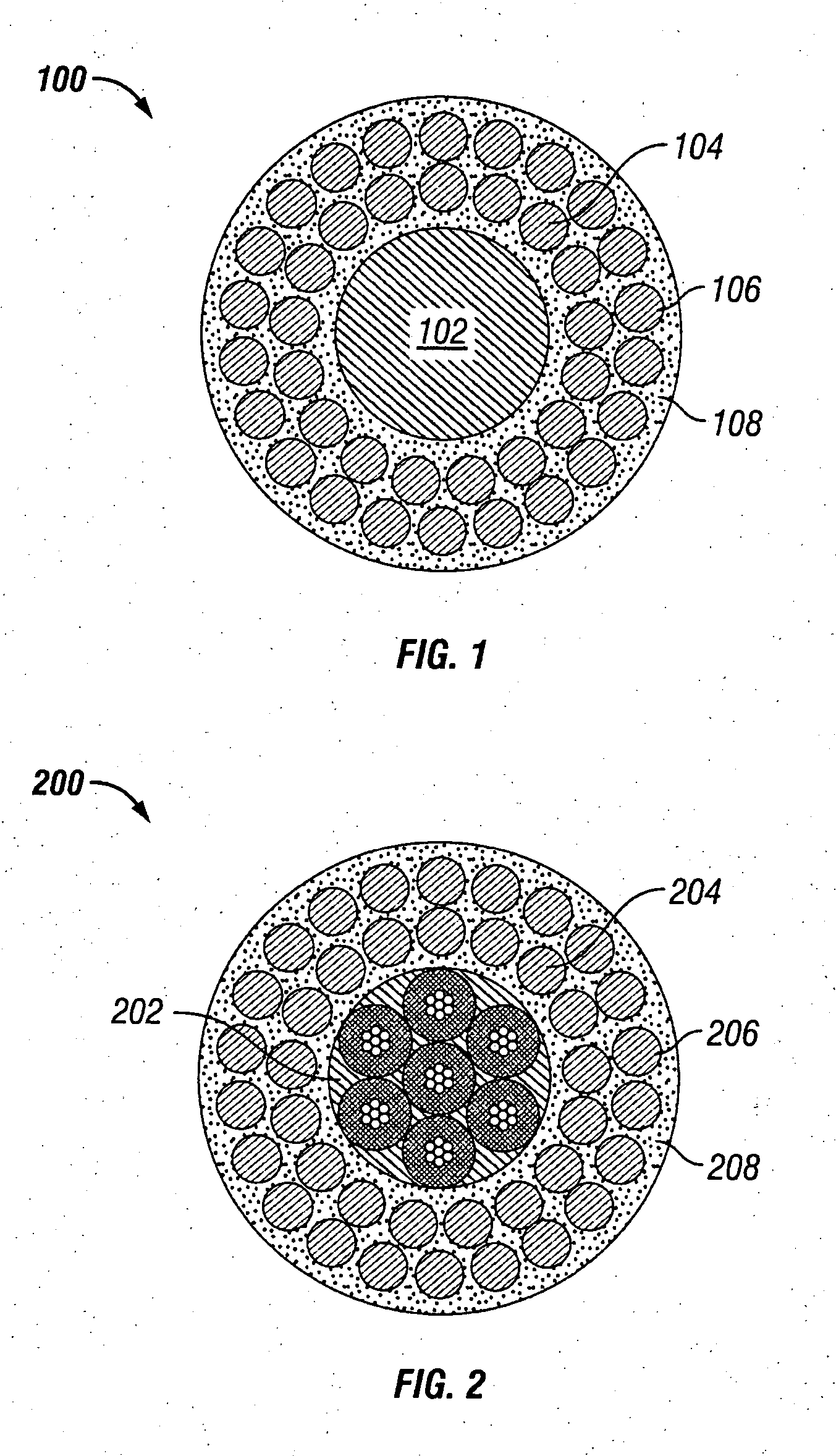
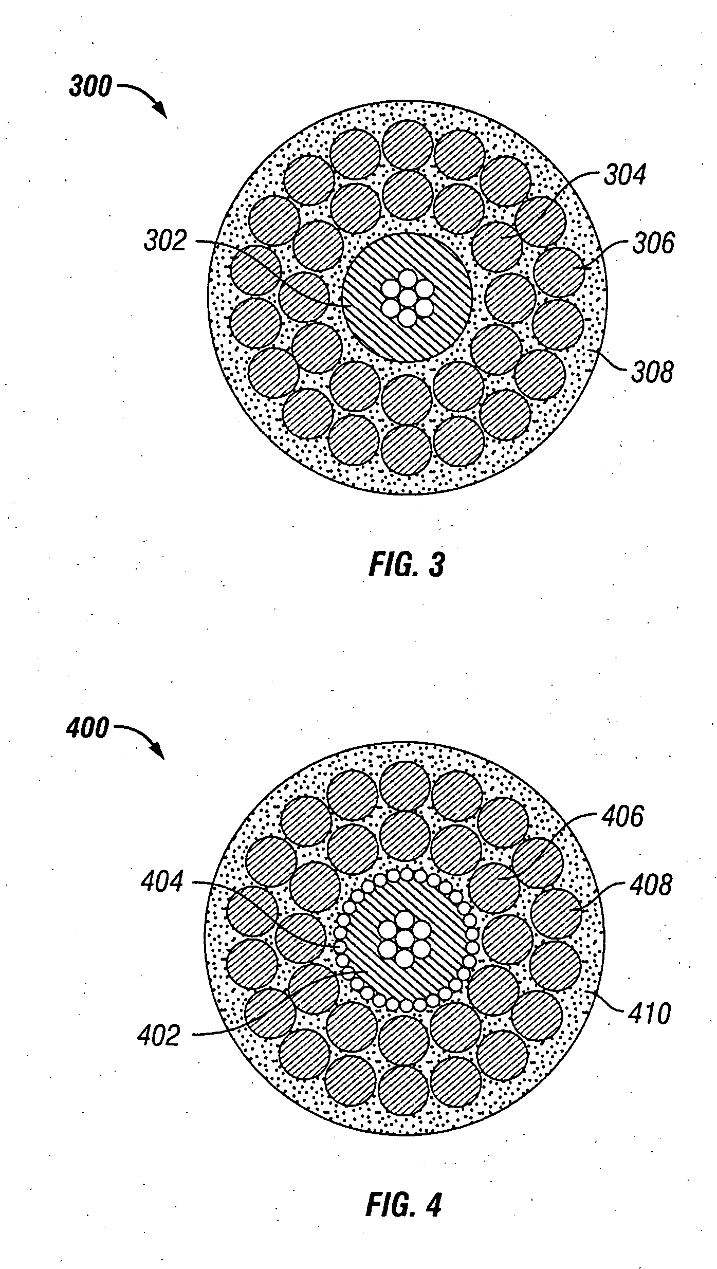
[0013] In one aspect of the invention, methods of manufacturing electrical cables are provided. In one embodiment of the invention, a method for manufacturing a wellbore electric cable, the method includes providing at least one insulated conductor, extruding a first polymeric material layer over the insulated conductor, serving a first layer of armor wires around the polymeric material and embedding the armor wires in the first polymeric material by exposure to an electromagnetic radiation source, followed by and extruding a second polymeric material layer over the first layer of armor wires embedded in the first polymeric material layer. Then, a second layer of armor wires may be served around the second polymeric material layer, and embedded therein by exposure to an electromagnetic radiation source. Finally, a third polymeric layer may be extruded around the second layer of armor wires to form a polymeric jacket. The polymeric material may be a polyolefin, polyamide, polyurethane, thermoplastic polyurethane, polyaryletherether ketone, polyaryl ether ketone, polyphenylene sulfide, polymers of ethylene-tetrafluoroethylene, polymers of poly(1,4-phenylene), polytetrafluoroethylene, perfluoroalkoxy polymers, fluorinated ethylene propylene, perfluoromethoxy polymers, ethylene chloro-trifluoroethylene (such as Halar®), chlorinated ethylene propylene, and any mixtures thereof, and may further include wear resistance particles or even reinforcing short and / or milled fibers. The cable formed may be a monocable, a quadcable, a heptacable, a quadcable, or a coaxial cable, and used in wellbore or seismic operations. Also, the method may be utilized to form insulated stranded conductors useful to make cables.

Problems solved by technology

Formations generally comprising shale, which may also encapsulate oil-bearing formations, may have porosities much greater than that of sandstone or limestone, but, because the grain size of shale is very small, it may be very difficult to remove the oil or gas trapped therein.
Commonly, the useful life of a wellbore electric cable is typically limited to only about 6 to 24 months, as the cable may be compromised by exposure to extremely corrosive elements, or little or no maintenance of cable strength members, such as armor wires.
A common factor limiting cable life is armor wire failure, where fluids present in the downhole wellbore environment lead to corrosion and failure of the armor wires.
While zinc protects the steel at moderate temperatures, it is known that corrosion is readily possible at elevated temperatures and certain environmental conditions.
Although the cable core may still be functional, it is generally not economically feasible to replace the armor wire, and the entire cable must be discarded.
Once corrosive fluids infiltrate into the annular gaps, it is difficult or impossible to completely remove them.
Even after the cable is cleaned, the corrosive fluids remain in interstitial spaces damaging the cable.
Once the armor wire begins to corrode, strength is quickly lost, and the entire cable must be replaced.
Armor wires in wellbore electric cables are also associated with several operational problems including torque imbalance between armor wire layers, difficult-to-seal uneven outer profiles, and loose or broken armor wires.
Because the armor wire layers have unfilled annular gaps or interstitial spaces, dangerous gases from the well can migrate into and travel through these gaps upward toward lower pressure.
As the cable goes over the upper sheave at the top of the piping, the armor wires may spread apart, or separate slightly, and the pressurized gas released, where it becomes a fire or explosion hazard.
Further, while the cables with two layers of armor wires are under tension, the inner and outer armor wires, generally cabled at opposite lay angles, rotate slightly in opposite directions causing torque imbalance problems.
To create a torque-balanced cable, inner armor wires would have to be somewhat larger than outer armor wires, but the smaller outer wires would quickly fail due to abrasion and exposure to corrosive fluids.
Therefore, larger armor wires are placed at the outside of the wireline cable, which results in torque imbalance.
Armored wellbore cables may also wear due to point-to-point contact between armor wires.
While under tension and when cables go over sheaves, radial loading causes point loading between outer and inner armor wires.
This may cause strength reduction, lead to premature corrosion, and may even accelerate cable fatigue failure.
Also, due to annular gaps or interstitial spaces between the inner armor wires and the cable core, as the wireline cable is under tension the cable core materials tend to creep thus reducing cable diameter and causing linear stretching of the cable as well as premature electrical shorts.
This bouncing motion creates rapidly changing tension and torque, which can cause several problems.
This type of design has several problems, such as, when the jacket is damaged, harmful well fluids enter and are trapped between the jacket and the armor wire, causing corrosion, and since damage occurs beneath the jacket, it may go unnoticed until a catastrophic failure.
Also, during wellbore operations, such as logging, in deviated wells, wellbore cables make significant contact with the wellbore surface.
The spiraled ridges formed by the cables' armor wire commonly erode a groove in the side of the wellbore, and as pressure inside the well tends to be higher than pressure outside the well, the cable is prone to stick into the formed groove.
Further, the action of the cable contacting and moving against the wellbore wall may remove the protective zinc coating from the armor wires, causing corrosion at an increased rate, thereby reducing the cable life.

Method used


Image

  • Methods of manufacturing enhanced electrical cables
  • Methods of manufacturing enhanced electrical cables
  • Methods of manufacturing enhanced electrical cables

Examples


Embodiment Construction

[0034] Illustrative embodiments of the invention are described below. In the interest of clarity, not all features of an actual implementation are described in this specification. It will of course be appreciated that in the development of any such actual embodiment, numerous implementation-specific decisions must be made to achieve the developer's specific goals, such as compliance with system related and business related constraints, which will vary from one implementation to another. Moreover, it will be appreciated that such a development effort might be complex and time consuming but would nevertheless be a routine undertaking for those of ordinary skill in the art having the benefit of this disclosure.

[0035] The invention relates to methods of manufacturing electric cables, as well as cables and the use of cables manufactured by such methods. In one aspect, the invention relates to a method of manufacturing durable and sealed torque balanced enhanced electric cable used with ...


PUM

PropertyMeasurementUnit
relative permittivityaaaaaaaaaa
outer diameteraaaaaaaaaa

Abstract

Disclosed are methods of manufacturing electrical cables. In one embodiment of the invention, method for manufacturing a wellbore cable includes providing at least one insulated conductor, extruding a first polymeric material layer over the insulated conductor, serving a first layer of armor wires around the polymeric material and embedding the armor wires in the first polymeric material by exposure to an electromagnetic radiation source, followed by and extruding a second polymeric material layer over the first layer of armor wires embedded in the first polymeric material layer. Then, a second layer of armor wires may be served around the second polymeric material layer, and embedded therein by exposure to an electromagnetic radiation source. Finally, a third polymeric layer may be extruded around the second layer of armor wires to form a polymeric jacket.

Description

BACKGROUND OF THE INVENTION [0001] 1. Field of the Invention [0002] This invention relates to methods of manufacturing electric cables, as well as cables and the use of cables manufactured by such methods. In one aspect, the invention relates to a method of manufacturing durable and sealed torque balanced enhanced electric cables used with wellbore devices to analyze geologic formations adjacent a wellbore. [0003] 2. Description of the Related Art [0004] Generally, geologic formations within the earth that contain oil and / or petroleum gas have properties that may be linked with the ability of the formations to contain such products. For example, formations that contain oil or petroleum gas have higher electrical resistivity than those that contain water. Formations generally comprising sandstone or limestone may contain oil or petroleum gas. Formations generally comprising shale, which may also encapsulate oil-bearing formations, may have porosities much greater than that of sandsto...

Claims


Application Information

Patent Timeline
Patent Type & Authority Applications(United States)
IPC IPC(8): H02G3/04
CPCH01B7/046H01B13/26Y10T29/49117Y10T29/5193Y10T29/49194Y10T29/49169Y10T29/49123
Inventor VARKEY, JOSEPH P.KIM, BYONG JUN
Owner SCHLUMBERGER TECH CORP
Why Eureka
Try Eureka