Tiltable construction laser

a construction laser and tilting technology, applied in the direction of height/levelling measurement, instruments, surveying and navigation, etc., can solve the problems of complex measurement frame, cumbersome additional tiltable sub-assembly, and total error of indirect determination of inclination, so as to achieve the effect of simple technology

Active Publication Date: 2006-11-02
HILTI AG
View PDF14 Cites 29 Cited by
  • Summary
  • Abstract
  • Description
  • Claims
  • Application Information

AI Technical Summary

Benefits of technology

[0010] An object of the present invention is a tiltable construction laser which is simple in terms of technology.

Problems solved by technology

The measurement frame, as additional tiltable subassembly, is complicated.
In addition, the errors of the leveling sensor and angle sensor accumulate to a total error in this indirect determination of inclination.

Method used


Image

  • Tiltable construction laser
  • Tiltable construction laser
  • Tiltable construction laser

Examples


Embodiment Construction

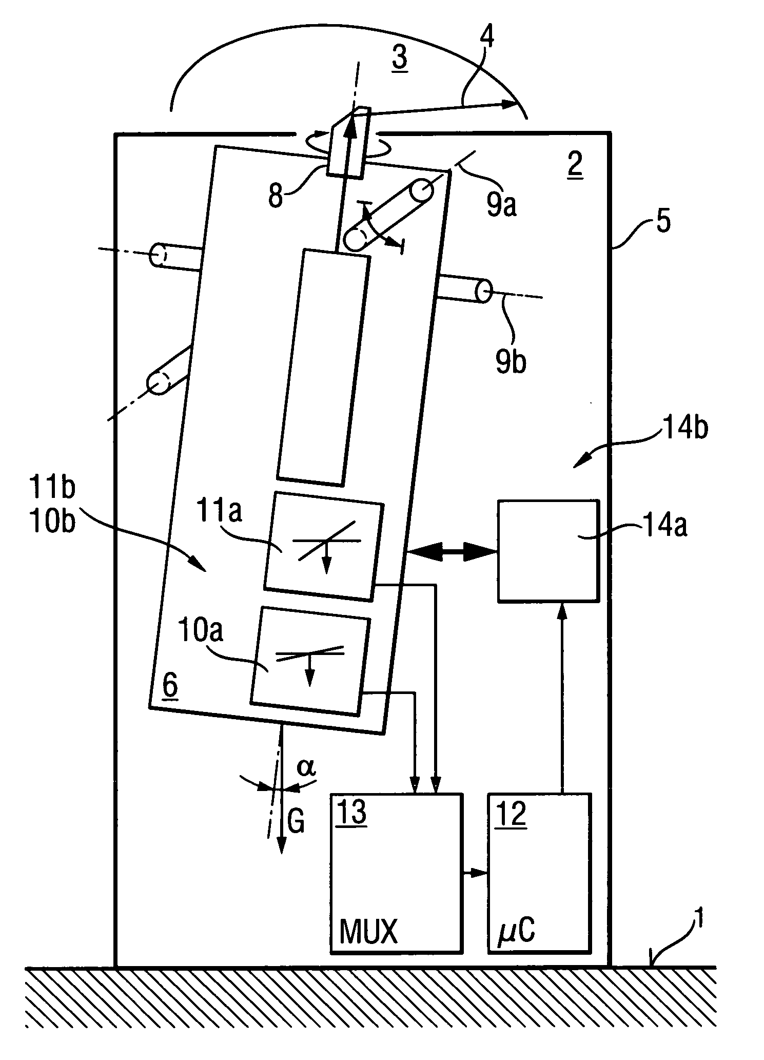
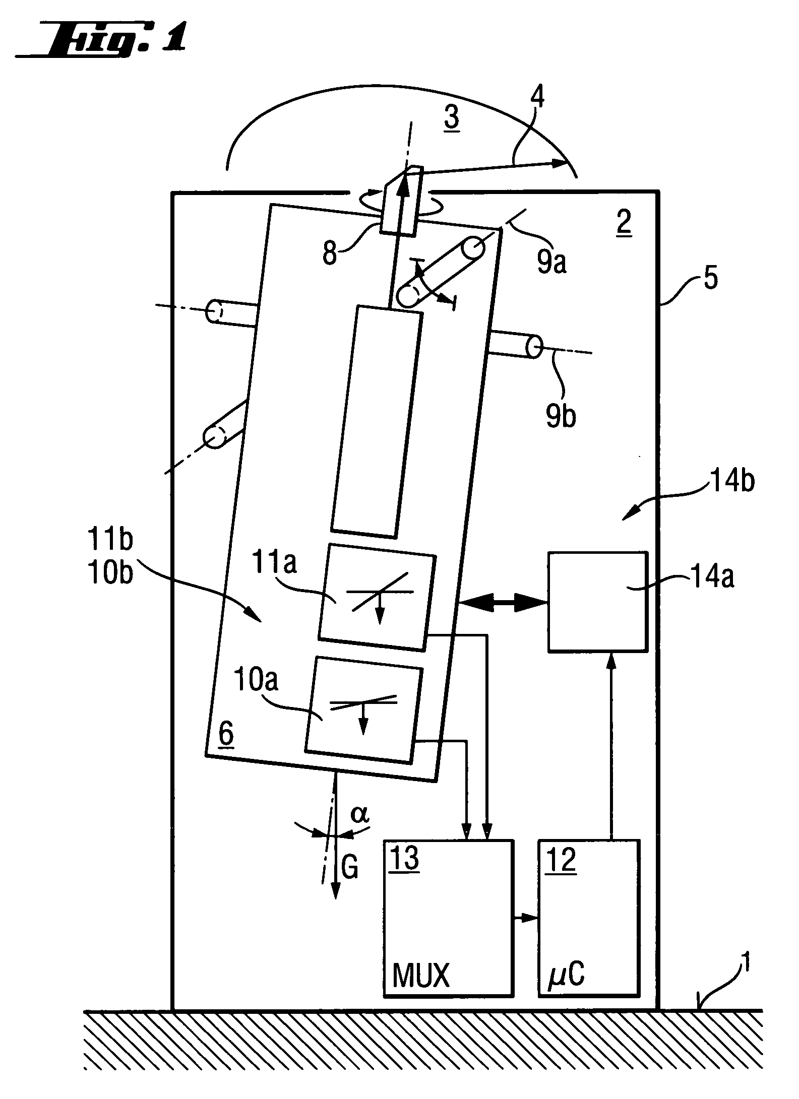
[0028] According to FIG. 1, a construction laser 2 which is set up on a supporting surface 1 and which is formed as a rotating construction laser with a laser beam 4 which rotates continuously within a plane 3, has a housing 5, a laser unit 6 with a laser light source 7 located in the housing 5, and a rotating deflecting prism 8. The laser unit 6 is tiltable about a swiveling axis 9a with respect to the housing 5. A leveling sensor 10a with a high angular resolution and a narrow tilt measurement range for highly precise orientation to the gravitational field G, and a tilt sensor 11a with a smaller angular resolution and a broader tilt measurement range for direct measurement of an inclination angle [alpha] relative to the gravitational field G are provided in the laser unit 6 so as to be sensitive to the swiveling axis 9a. A multiplexer 13 for serial measurement value acquisition is arranged between the sensors, which are unidimensionally sensitive (leveling sensor 10a and tilt sens...


PUM


Abstract

A construction laser with at least one laser beam (4) defining a plane (3) has a laser unit (6) which is tiltable with respect to a housing (5) around at least one swiveling axis (9a) and includes at least one leveling sensor (10a) which is sensitive to the swiveling axis (9a) for a highly precise orientation to the gravitational field (G), and at least one tilt sensor (11a) which is sensitive to the swiveling axis (9a) for direct measurement of an inclination angle [alpha] relative to the gravitational field (G).

Description

BACKGROUND OF THE INVENTION [0001] 1. Field of the Invention [0002] The invention is directed to a tiltable construction laser, particularly a tiltable rotating construction laser with a laser beam that is moved within a plane at least by segments. [0003] 2. Description of the Prior Art [0004] Construction lasers with a fanned out laser beam or with a plurality of laser beams defining a plane and rotating construction lasers with a laser beam that is moved within a plane at least by segments, are used primarily in the building industry to determine horizontal planes, vertical planes, or planes at defined inclinations on walls, ceilings and floors. In this connection, particularly when leveling horizontal planes and vertical planes, strict requirements are imposed for orientation to the earth's gravitational field with maximum deviations of less than 10″ (angular seconds) for the total error of the system. The sensors themselves account for about 3″ to 5″ of this total error. On the ...

Claims


Application Information

Patent Timeline
Patent Type & Authority Applications(United States)
IPC IPC(8): G01C5/00
CPCG01C15/008G01C15/004Y10S33/21
Inventor AMMANN, MANFREDKOUSEK, HEINZ
Owner HILTI AG
Why Eureka
Try Eureka