Floating power plant

a technology of floating power plants and power plants, which is applied in the direction of special-purpose vessels, machine/engines, vessel construction, etc., can solve the problems of power consumption by power consumers, the determination of the location of the power plant may be accompanied by further practical limitations, and the difficulty of placing the facilities of the power plant in desirable locations, etc., to achieve the effect of minimizing the limitations caused by environmental regulations

Inactive Publication Date: 2006-11-02
KIM MI YEONG
View PDF6 Cites 13 Cited by
  • Summary
  • Abstract
  • Description
  • Claims
  • Application Information

AI Technical Summary

Benefits of technology

[0011] Another object of the present invention is to provide a floating power plant, which can economically supply electricity to a specific district or to a specific facility that temporarily uses electricity, and which minimizes the limitations caused by environmental regulations, and can be used as an emergency electric power source.

Problems solved by technology

However, the above-mentioned power plants are problematic in that it is very difficult to locate the facilities of the power plants in desirable locations, and the power plants impose a large initial investment on the owners.
Furthermore, the locations of the power plants have been determined in consideration of environmental impact assessments, the possibility of disasters based on the geological characteristics of selected districts, the expected impacts of accidents on neighboring industrial facilities or explosive material storage facilities, the supply of fuel and water required to operate the power plants, and the expected power consumption by power consumers using electricity supplied by the power plants.
In recent years, power plants have become recognized as harmful facilities, so it is necessary to pay careful attention to trends of public opinion of local inhabitants or of nongovernmental organizations (NGO), in addition to consideration of the conditions at locations.
Thus, the determination of the locations of the power plants may be accompanied by further practical limitations.
Furthermore, in the case of a specific district, where a great quantity of electricity must be temporarily used, or of a district under development, which requires a great quantity of electricity, it is necessary to build a new power plant at the district to meet the electricity requirements of the district because there is no alternative plan.
However, the installation of a new power plant in such a district must be accompanied by high investment and time consumption.
Furthermore, if the amount of electric power consumption is remarkably reduced, or if the facilities using the electricity are removed, so that the use of electricity is discontinued, the power plant built in the specific district suffers from economic inefficiency.
However, the extension of the power supply network limits the quantity of electricity that can be supplied to the district.

Method used


Image

  • Floating power plant
  • Floating power plant
  • Floating power plant

Examples


Embodiment Construction

[0023] Reference will now be made in greater detail to a preferred embodiment of the present invention, an example of which is illustrated in the accompanying drawings. Wherever possible, the same reference numerals will be used throughout the drawings and the description to refer to the same or like parts.

[0024] Herein below, a floating power plant according to a preferred embodiment of the present invention will be described with reference to the accompany drawings.

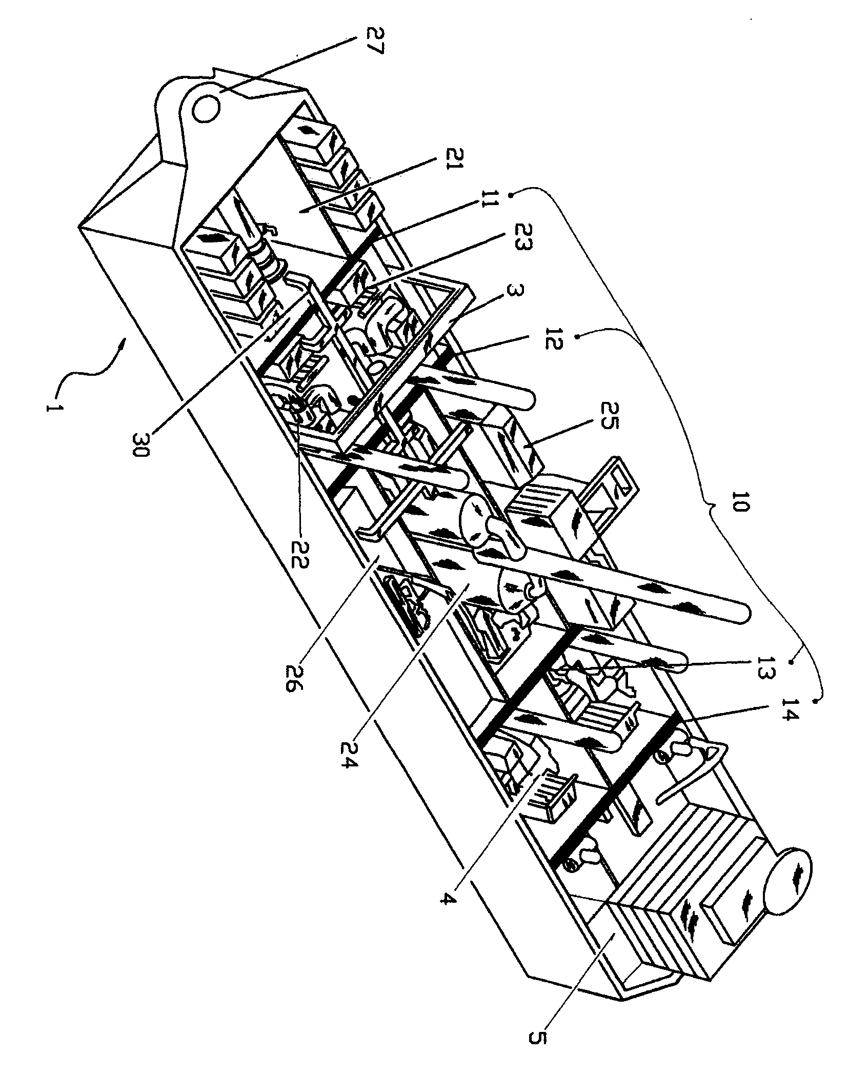
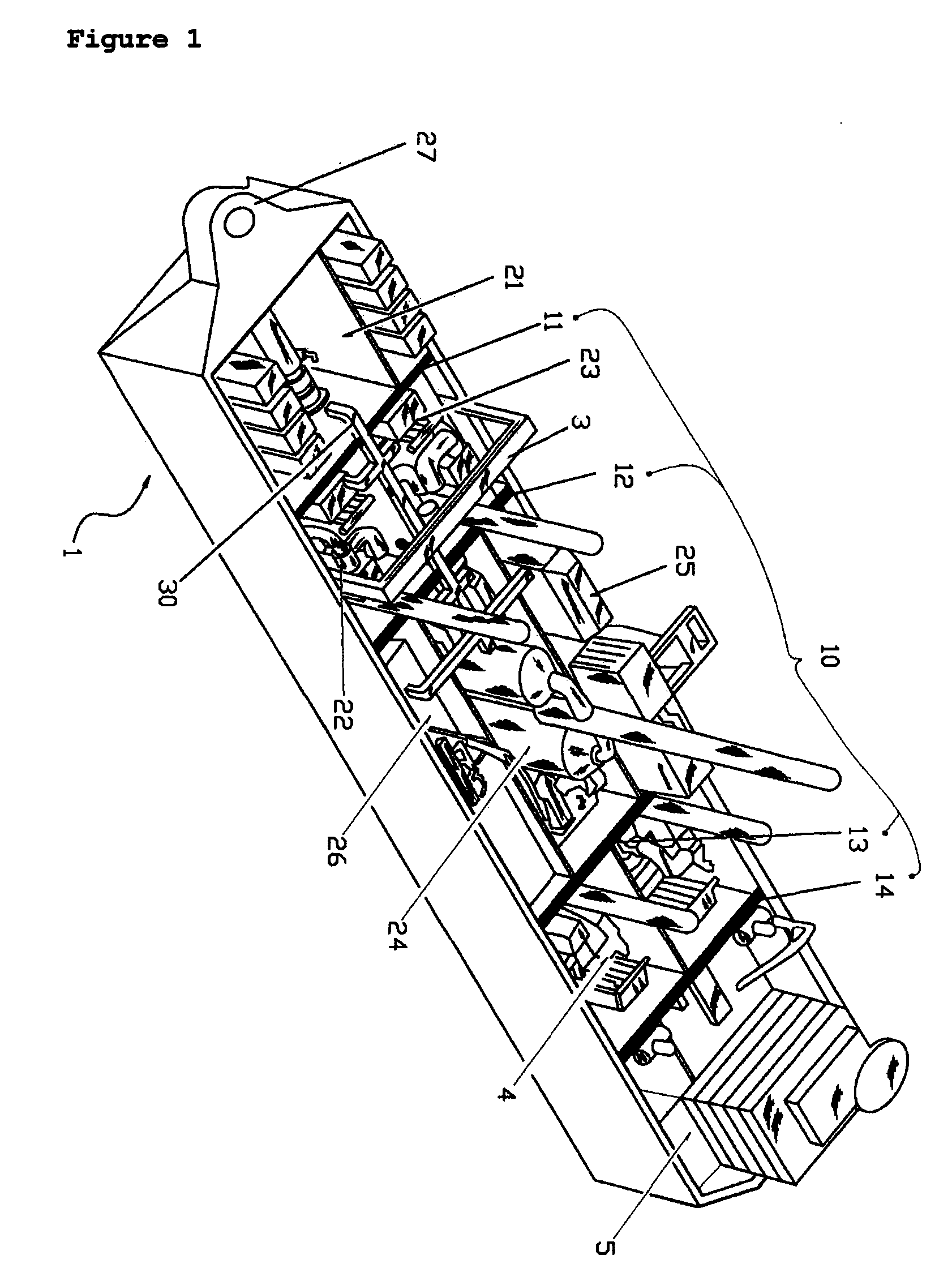
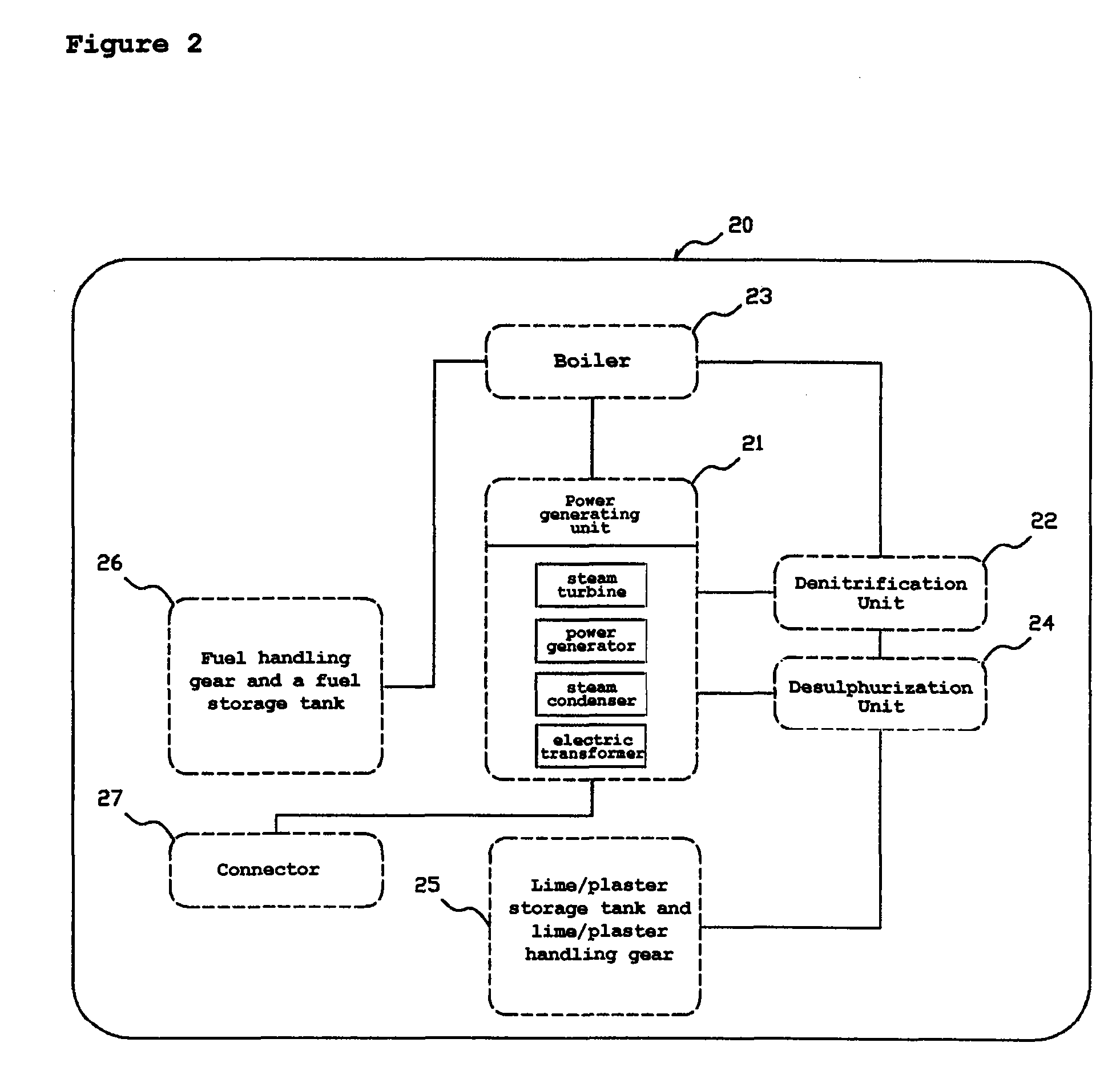
[0025]FIG. 1 is a perspective view illustrating a floating power plant according to the present invention. FIG. 2 is a block diagram illustrating the construction of a power generating means provided in the floating power plant according to the present invention.

[0026] As shown in the drawings, the floating power plant according to the preferred embodiment of the present invention comprises a hull 1 having a structure suitable for being movable on the sea. A plurality of watertight bulkheads 10 is placed in the hull ...


PUM


Abstract

Disclosed is a floating power plant. The floating power plant includes a hull having a structure suitable for being movable at sea; a plurality of watertight bulkheads placed in the hull to a height of a freeboard deck, thus partitioning the interior of the hull into a plurality of watertight chambers; a power generating means for generating electricity, the power generating means including a plurality of parts separately installed in the watertight chambers; and a duct arranged to pass over the freeboard deck to couple the parts of the power generating means installed in the watertight chambers to each other. Because the floating power plant, provided with the power generating means, is freely movable at sea, the floating power plant can economically supply electricity to a specific district or to a specific facility that temporarily uses electricity, and can minimize limitations caused by environmental regulations, and can be used as an emergency electric power source. Thus, the floating power plant remarkably increases the degree of freedom while forming and managing an energy policy. Furthermore, the present invention overcomes problems of conventional land power plants and, particularly, solves the problem of the waste of land caused by construction of power plants on land, and thus reduces environmental pollution.

Description

BACKGROUND OF THE INVENTION [0001] 1. Field of the Invention [0002] The present invention relates, in general, to floating power plants and, more particularly, to a floating power plant, which can is freely movable on the sea and does not require separate flumes for water or adjacent piers for the supply of generating fuel. [0003] 2. Description of the Related Art [0004] Generally, power plants comprise equipment for converting thermal energy or mechanical energy into electrical energy, rotate a turbine using an energy source, such as water, oil, coal, natural gas, or nuclear power, and generate electricity using a power generator connected to the turbine. Such power plants have typically been classified into water power plants, steam power plants, nuclear power plants, etc. according both to the kind of energy source used in the power plants and to the power generation method. Furthermore, tidal power plants, using tidal energy, wind power plants, using wind energy, geothermal powe...

Claims


Application Information

Patent Timeline
Patent Type & Authority Applications(United States)
IPC IPC(8): B63B35/44
CPCB63B11/02B63B35/44F22B37/54F01K13/00F01K15/00B63B2035/4433F01K15/04
Inventor PARK, JAE-WOOK
Owner KIM MI YEONG
Why Eureka
Try Eureka