Muffler with improved heat dissipation

Inactive Publication Date: 2006-11-02
SAMSON MOTORCYCLE PRODS
View PDF17 Cites 14 Cited by
  • Summary
  • Abstract
  • Description
  • Claims
  • Application Information

AI Technical Summary

Benefits of technology

[0015] Desirably, there is included heat-resistant fibrous material in the elongated inner chamber to enhance sound reduction.

Problems solved by technology

Internal combustion engines and turbines produce exhaust combustion gases and the discharged exhaust is frequently accompanied by undesirable levels of noise.
Moreover, the hot exhaust gas quickly heats the outer wall of the muffler to a temperature approaching that of the exhaust gas and prolonged high temperature can produce discoloration of the cosmetic finish on the outer wall.
However, the outer wall of the muffler reaches temperatures approaching that of the exhaust gas passing therethrough and discoloration of the cosmetic coating may occur.

Method used


Image

  • Muffler with improved heat dissipation
  • Muffler with improved heat dissipation
  • Muffler with improved heat dissipation

Examples


Embodiment Construction

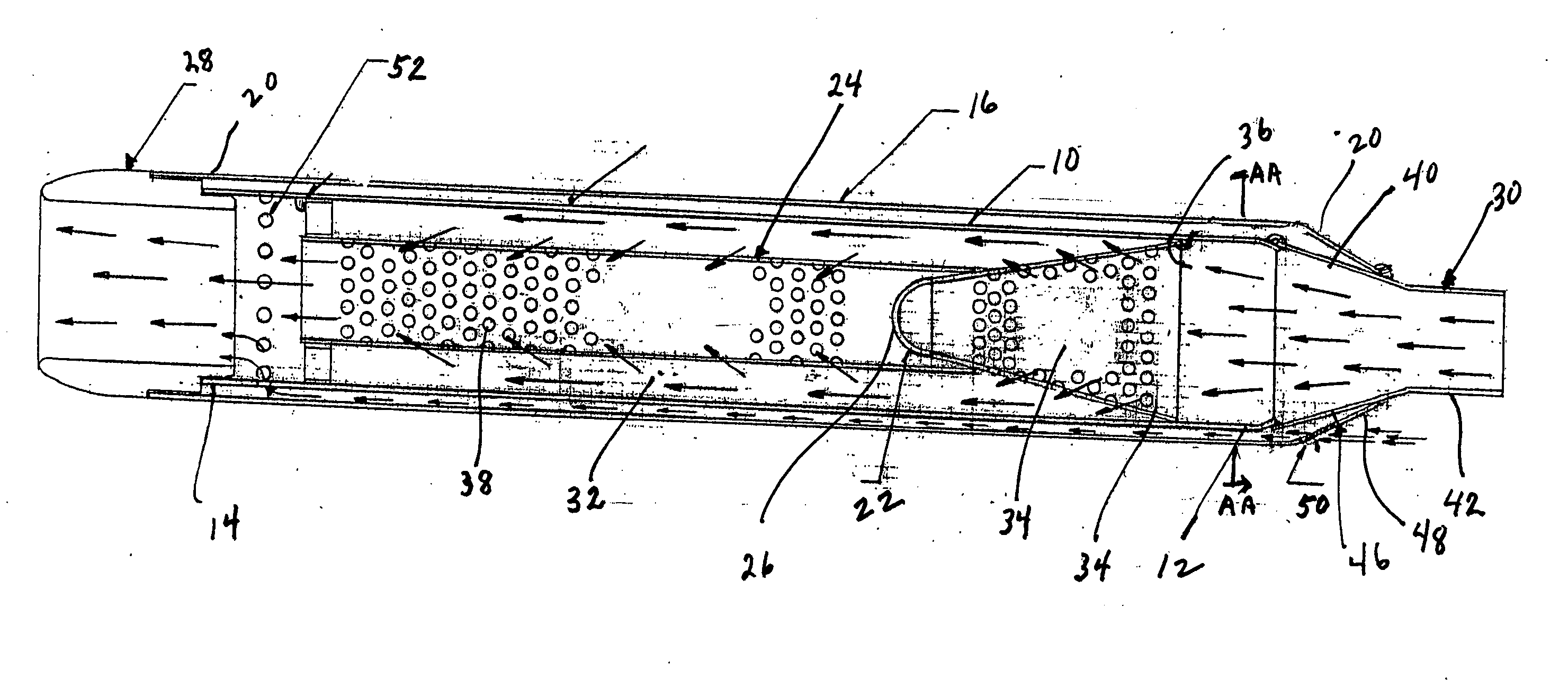
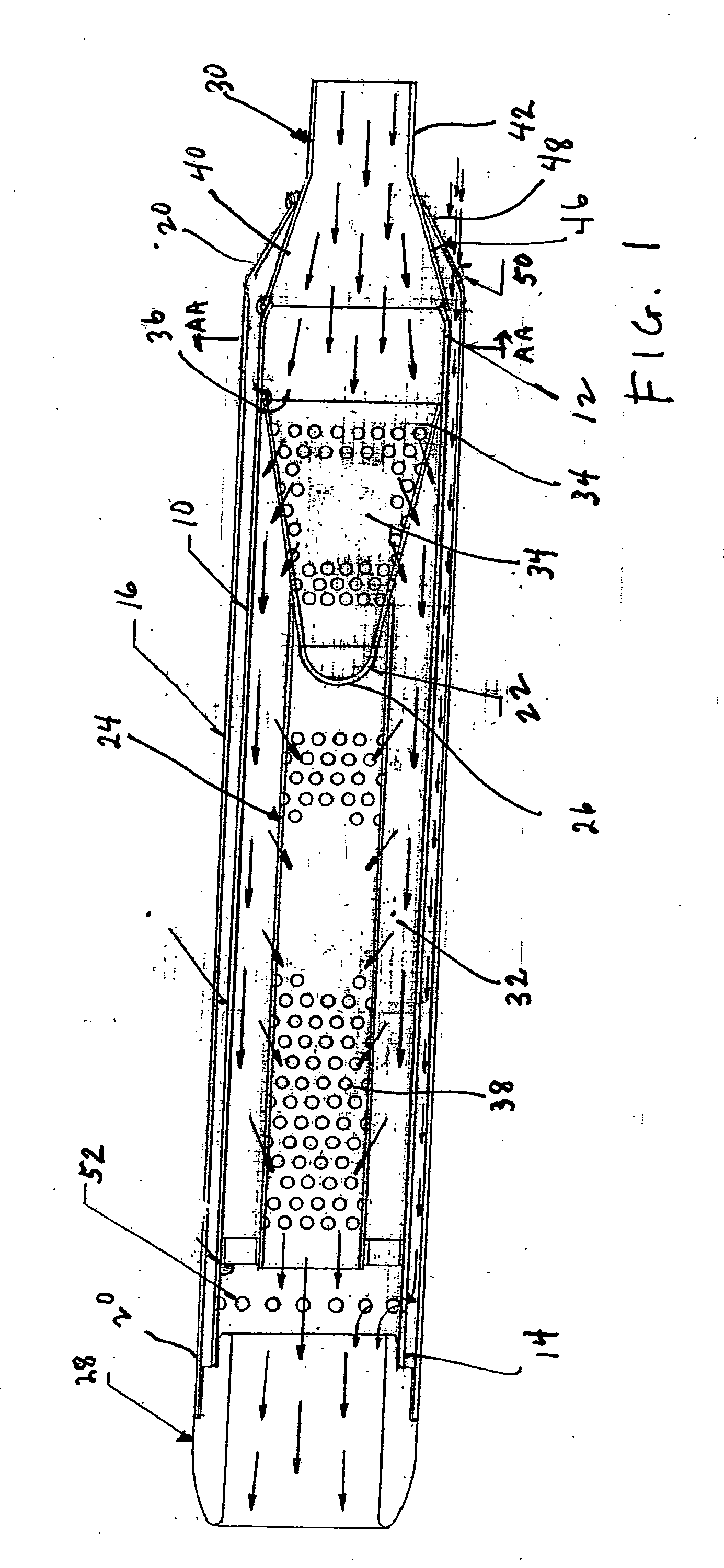
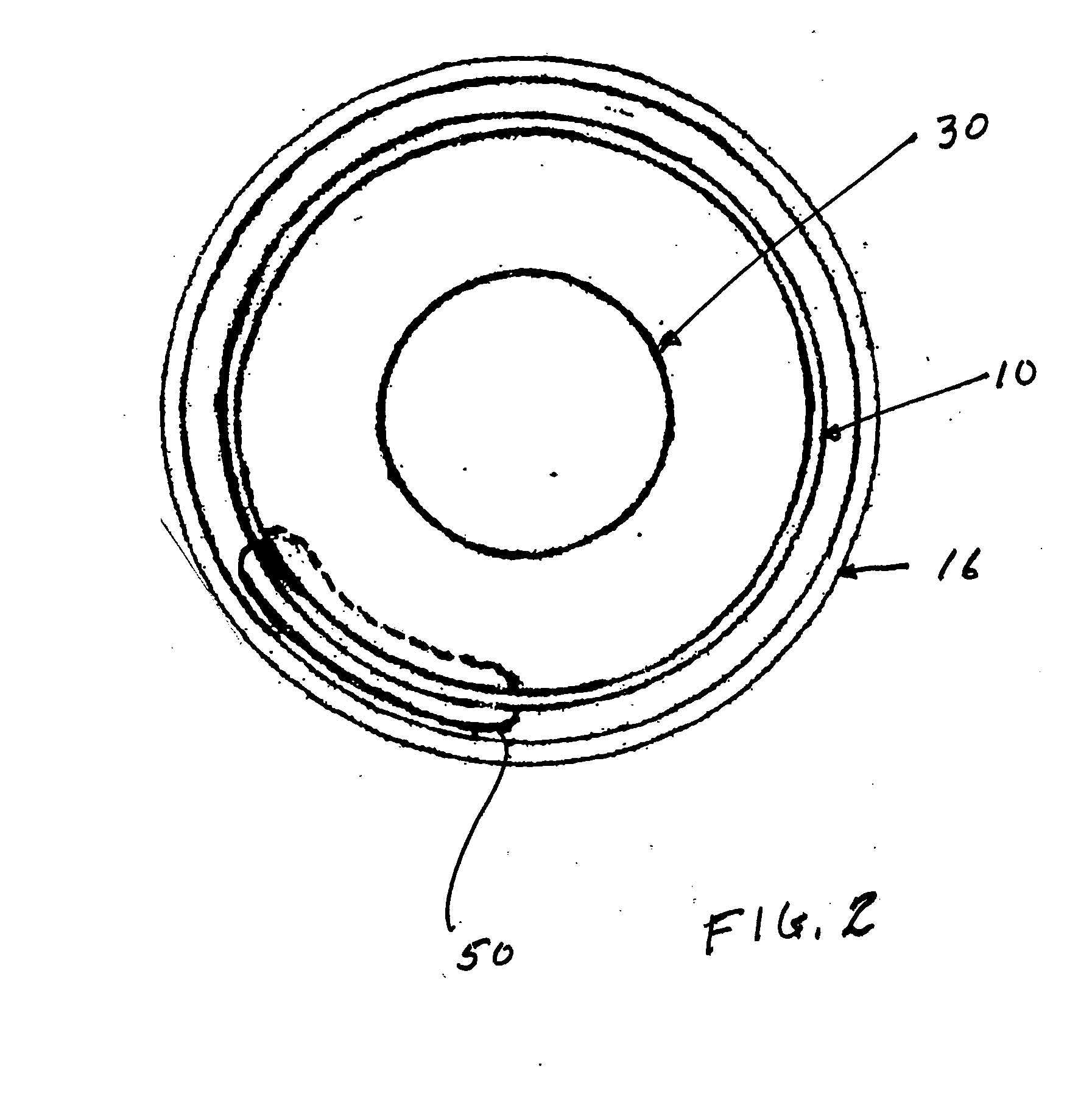
[0018]FIG. 1 illustrates an engine muffler / exhaust extractor embodying the present invention which is generally comprised of an inner tubular or cylindrical casing generally designated by the numeral 10 having an inlet end 12 and an outlet end 14, and an outer tubular or cylindrical casing generally designated by the numeral 16 having an inlet end 18 and an outlet end 20.

[0019] Seated within the inner casing 10 adjacent its inlet end 12 is a frustoconical baffle generally designated by the numeral 22. Also seated within the casing 10 is a cylindrical baffle generally designated by the numeral 24 which extends over the small diameter end portion 26 of the frustoconical baffle 22 and is supported adjacent the discharge end by the support cap generally designated by the numeral 28. At the inlet end of the casing 10 is an inlet fitting generally designated by the numeral 30. The baffles 22 and 24 are dimensioned so that there is an annular space between them and the inner casing 10 pro...


PUM


Abstract

A muffler has inner and outer elongated concentric and radially spaced generally cylindrical casings having inlet and outlet ends, and providing an annular chamber therebetween. The outer casing has an inlet opening into the annular chamber adjacent the inlet end of the outer casing so that air may flow to the outer end. The inner casing has an aperture adjacent the outlet end for the air to flow from the annular chamber into the inner casing for discharge with the exhaust. This air flow through the annular chamber reduces the temperature of the outer casing from that of the inner casing. Baffles are provided in the inner casing, and insulating material may also be provided in the inner casing.

Description

BACKGROUND OF THE INVENTION [0001] This invention is related to exhaust systems, and, more particularly, to a muffler which will facilitate exhaust action and noise abatement of high velocity exhaust gas flow and which has an outer wall which has a reduced temperature. [0002] Internal combustion engines and turbines produce exhaust combustion gases and the discharged exhaust is frequently accompanied by undesirable levels of noise. The problem of muffling and evacuating such exhaust gases is well known. [0003] Moreover, the hot exhaust gas quickly heats the outer wall of the muffler to a temperature approaching that of the exhaust gas and prolonged high temperature can produce discoloration of the cosmetic finish on the outer wall. [0004] In my U.S. Pat. No. 6,510,921 granted Jan. 8, 2003, I have described an improved muffler which contains a pair of baffle elements in a construction which reduces back pressure and facilitates extraction of the exhaust from the engine. However, the ...

Claims


Application Information

Patent Timeline
IPC IPC(8): F01N7/08F01N1/00F01N13/08
CPCF01N1/08F01N1/083F01N1/24F01N2470/24F01N2270/02F01N2470/02F01N2260/022
Inventor PRICE, KENNETH E.
Owner SAMSON MOTORCYCLE PRODS
Why Eureka
Try Eureka