Blue excited yellow fluorescent material and white light emitting element using the same

a technology of white light emitting element and fluorescent material, which is applied in the direction of discharge tube luminescnet screen, energy-saving lighting, sustainable buildings, etc., can solve the problems of inability to evenly mix emitted lights, and inability to achieve desired white light. achieve the effect of reliability and environmental resistan

Inactive Publication Date: 2006-11-02
MITSUI MINING & SMELTING CO LTD
View PDF5 Cites 2 Cited by
  • Summary
  • Abstract
  • Description
  • Claims
  • Application Information

AI Technical Summary

Benefits of technology

[0029] The blue excited yellow fluorescent material according to the present invention generates yellow light by blue light excitation, and shows a broad white light emitting spectrum over a range between 420 and 680 nm by combining blue light of the excitation light. Since the blue excited yellow fluorescent material uses an alkaline earth metal sulfide as the crystal base material, it excels in reliability and resistanc...

Problems solved by technology

However, these white light sources have problems in aspects of electric power consumption, size, operation life and the like.
However, when a light emitting diode is used as a light emitting element, there is a problem in that the light emitting diode has generally a light emitting spectrum having strong monochromaticity, and has no broad light emitting spectrum in the visible light region required for obtaining white light.
In this method, however, since the temperature characteristics and change in performance with time of individual diodes are different, there are problems such as that color tone and luminescence of each of red, green and blue color emitting vary, emitted lights cannot be evenly mixed, and color irregularity occurs; therefore, a desired white light cannot be obtained.
In addition, since the mate...

Method used


Image

  • Blue excited yellow fluorescent material and white light emitting element using the same
  • Blue excited yellow fluorescent material and white light emitting element using the same
  • Blue excited yellow fluorescent material and white light emitting element using the same

Examples


example 1

[0064] CaS, Ce2S3, and EU2S3 were used as materials, weighed so that the concentrations of Eu and Ce in the fluorescent material become 0.1 mol % and 0.5 mol %, respectively, and mixed for 90 minutes in a paint shaker using zirconia balls of a diameter of 3 mm as the media. Then, the mixed powder was separated from the media using a screen of 100 μm mesh or finer. Next, the mixed powder was annealed at 1180° C. for 6 hours in a hydrogen sulfide atmosphere, and further fired under entirely the same conditions to obtain a blue excited yellow fluorescent material represented by CaS:Ce, Eu (Example 1).

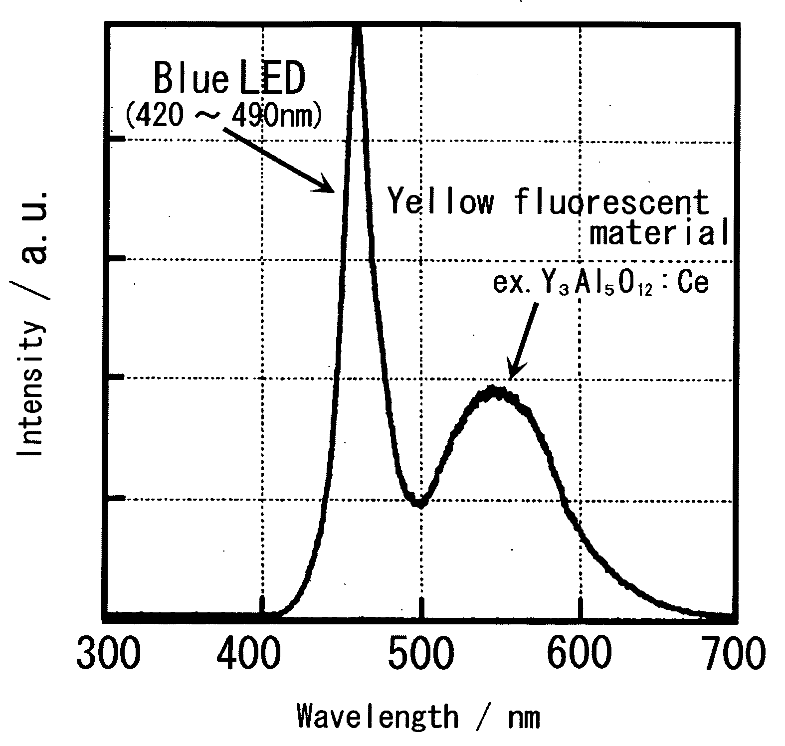
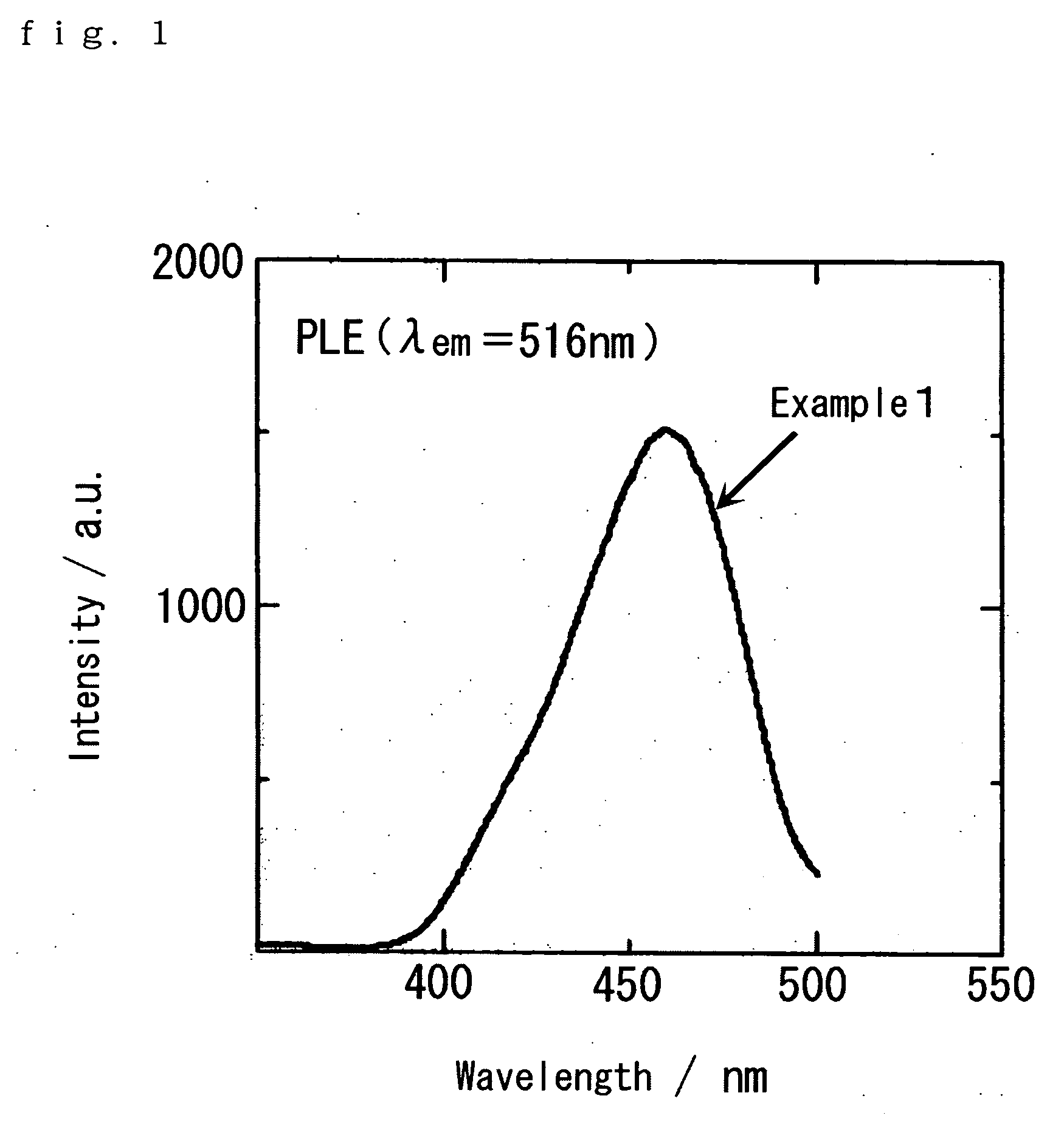
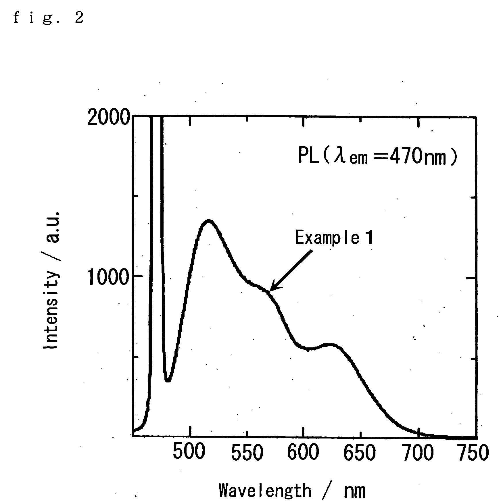
[0065] The excitation spectrum of the blue excited yellow fluorescent material is shown in FIG. 1, and the light emission spectrum thereof (excitation wavelength: 470 nm) is shown in FIG. 2. As obviously seen from FIG. 1, the excitation intensity of the yellow fluorescent material is the highest at the vicinity of a wavelength of 470 nm, and is similar to the peak wavelength of the light ...

example 2

[0066] CaS, Ce2S3, and EU2S3 were used as materials, weighed so that the concentrations of Eu and Ce in the fluorescent material became 0.1 mol % and 1.0 mol %, respectively, and mixed for 90 minutes in a paint shaker using zirconia balls of a diameter of 3 mm as the media. Then, the mixed powder was separated from the media using a screen of 100 μm mesh or finer. Next, the mixed powder was annealed at 1180° C. for 6 hours in a hydrogen sulfide atmosphere, and further fired under the same conditions to obtain a blue excited yellow fluorescent material represented by CaS:Ce, Eu (Example 2-1).

[0067] A blue excited yellow fluorescent material was obtained in the same manner as in Example 2-1 except that the quantity of Ce2S3 was changed so that the Ce concentration in the fluorescent material became 0.5 mol % (Example 2-2).

[0068] A blue excited yellow fluorescent material was obtained in the same manner as in Example 2-1 except that Ce2S3 was not added (Comparative Example 2-1).

[006...

example 3

[0070] CaS, SrS, Ce2S3, and Eu2S3were used as materials, weighed so that the concentrations of Eu and Ce in the fluorescent material became 0.1 mol % and 0.5 mol %, respectively in the composition of (Ca0.7Sr0.3)S:Eu,Ce, and mixed for 90 minutes in a paint shaker using zirconia balls of a diameter of 3 mm as the media. Then, the mixed powder was separated from the media using a screen of 100 μm mesh or finer. Next, the mixed powder was annealed at 1180° C. for 6 hours in a hydrogen sulfide atmosphere, further pulverized and mixed, and then fired under entirely the same conditions to obtain a blue excited yellow fluorescent material represented by (Ca0.7Sr0.3)S:Eu, Ce (Example 3).

[0071] The light emission spectrum of the blue excited yellow fluorescent material (excitation wavelength: 430 nm) was measured. The result is shown in FIG. 4. As is obviously seen from the comparison of Example 3 in FIG. 4 with Example 2-2 in FIG. 3, when Sr is added, the light emission spectrum shifts tow...


PUM


Abstract

There is provided a blue excited yellow fluorescent material that shows a broad light emitting spectrum ranging from green components to red components, is easy to control color tones, has high color rendering properties, and can provide white light close to natural light (sunlight), by combining with a blue light emitting element such as LED. To achieve the above features, a blue excited yellow fluorescent materials comprising an alkaline earth metal sulfide as a crystal base material, the fluorescent material activated by Ce3+ and Eu2+ or Mn2+ is used; and specifically, a blue excited yellow fluorescent material represented by (Ca1-xSrx)S:Ce, Eu or (Ca1-xSrx)S:Ce, Mn is preferably used.

Description

BACKGROUND OF THE INVENTION [0001] 1. Field of the Invention [0002] The present invention relates to a blue excited yellow fluorescent material containing an alkaline earth metal sulfide as a main component, and a white light emitting element using the same. Specifically, the present invention relates to a blue excited yellow fluorescent material containing an alkaline earth metal sulfide as a main component from which white light close to natural light can be obtained by combining with a blue light emitting element. [0003] 2. Description of the Related Art [0004] Heretofore, fluorescent lamps or incandescent lamps have been used as white light sources. However, these white light sources have problems in aspects of electric power consumption, size, operation life and the like. [0005] Since a light emitting diode (LED) is small and efficient, and can emit clear color light, demand as a light emitting element is expected. In addition, since a light emitting diode is a solid element, i...

Claims


Application Information

Patent Timeline
IPC IPC(8): H01J1/62H01L33/32H01L33/50H01L33/56
CPCC09K11/7718Y02B20/181H05B33/14C09K11/7786Y02B20/00
Inventor SASAKURA, ASUKAYANO, TOMOYASUITOH, JUN-ICHI
Owner MITSUI MINING & SMELTING CO LTD
Why Eureka
Try Eureka