Moving object detection device
- Summary
- Abstract
- Description
- Claims
- Application Information
AI Technical Summary
Benefits of technology
Problems solved by technology
Method used
Image

Examples
first embodiment
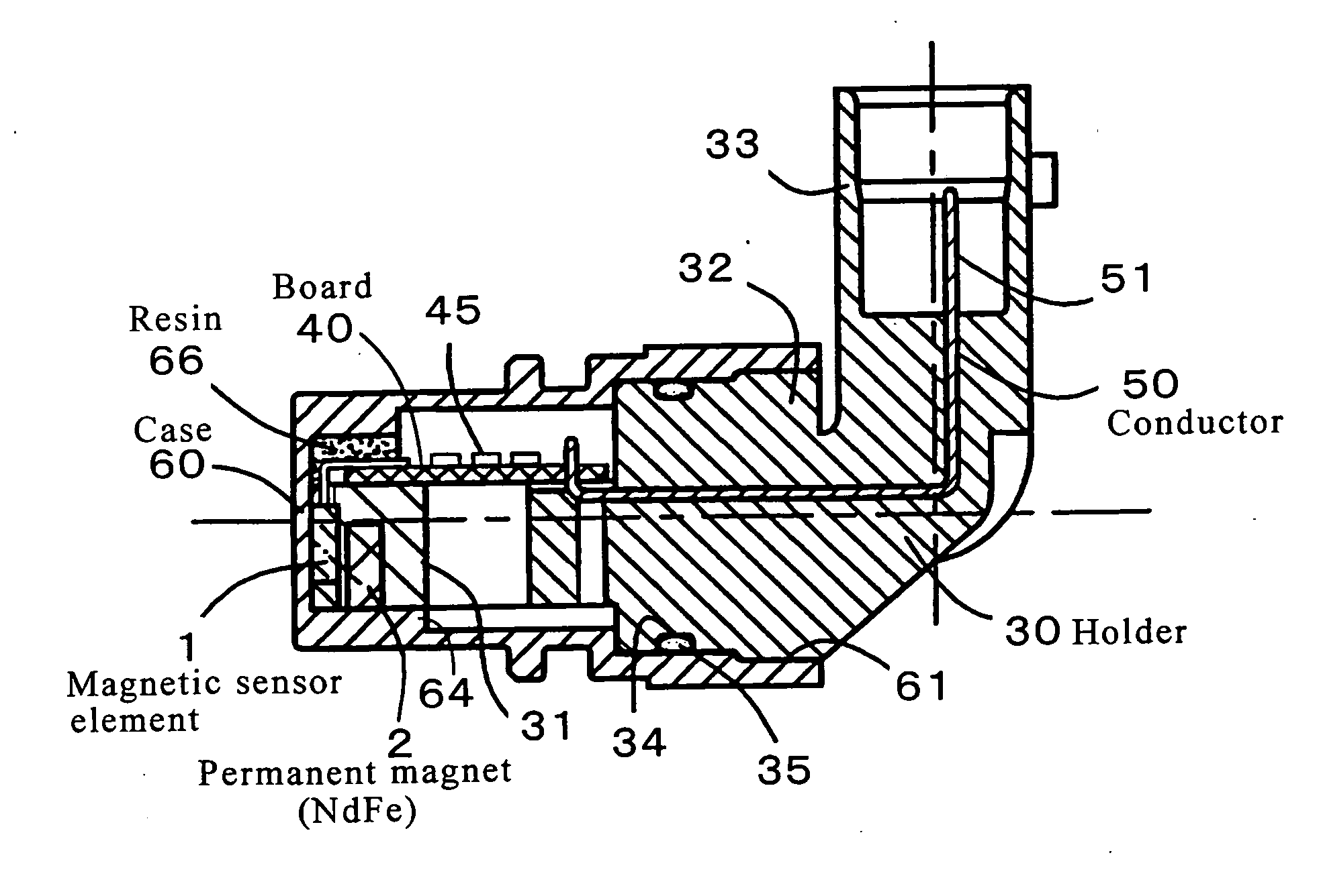
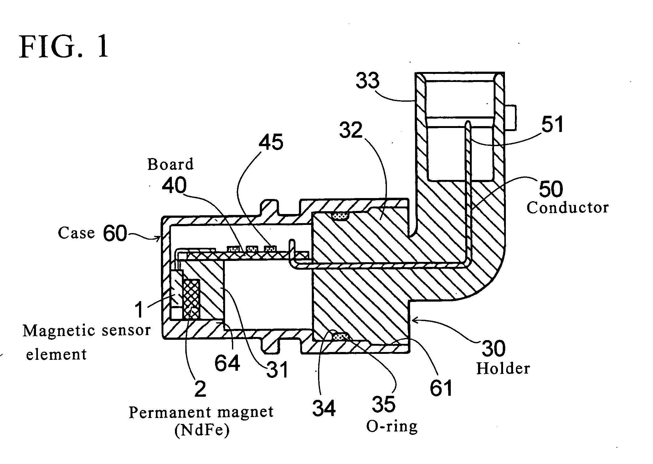
[0038] the invention is explained referring to FIG. 1 to FIG. 5. In FIG. 1 to FIG. 5, reference numeral 1 denotes a magnetic sensor element such as a Hall effect IC, reference numeral 2 for a permanent magnet made of NdFe magnet for applying a required bias magnetic field to the magnetic sensor element. The magnetic sensor element 1 and the permanent magnet 2 are arranged and held at a tip end of a support part 31 in the approximately box shape integrally formed on a holder 30 made of resin, and a board 40 is supported and fixed at an upper side of the support part 31. The magnetic sensor element 1 is connected to the board 40, on which circuit parts 45 (electronic parts such as IC, chip parts, etc.) for protecting (processing) an output signal of the magnetic sensor element 1 are implemented so as to assemble an output signal protection (processing) circuit.
[0039] The resin holder 30 has a columnar plug 32 and a connector 33 for connection. Each end of conductors 50 which penetrate...
second embodiment
[0052] the invention is explained referring to FIG. 6 to FIG. 9. In FIG. 7 and FIG. 9, a straight bar-shaped guide convex 37 is formed on both sides of the approximately box-shaped support part 31 that is integrally formed on the holder 3, and the direction of the guide convex 37 is the longitudinal direction of the support part 31.
[0053] As shown in FIG. 8B and FIG. 8D, guide concavities 65 as concave grooves engaging with the guide convexes 37 are formed on the inner surface of the case 60.
[0054] Therefore, the guide concavities 65 of the case 60 and the straight bar-shaped guide convex 37 are engaged, when the holder 30 and the case are fitted and fastened integrally each other. Thus, the support part 31 of the holder 30 is held by the case 60 without any vibration.
[0055] Before combining the case 60 with the holder 30, a resin 66 of un-hardening is put in a small quantity in an inner bottom part of the case 60. And the resin 66 stiffened after the combination of the case 60 wi...
PUM
 Abstract
Description
Claims
Application Information
 - R&D
- Intellectual Property
- Life Sciences
- Materials
- Tech Scout
- Unparalleled Data Quality
- Higher Quality Content
- 60% Fewer Hallucinations
Browse by: Latest US Patents, China's latest patents, Technical Efficacy Thesaurus, Application Domain, Technology Topic, Popular Technical Reports.
© 2025 PatSnap. All rights reserved.Legal|Privacy policy|Modern Slavery Act Transparency Statement|Sitemap|About US| Contact US: help@patsnap.com