

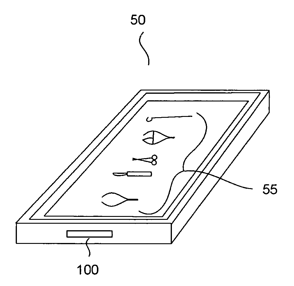
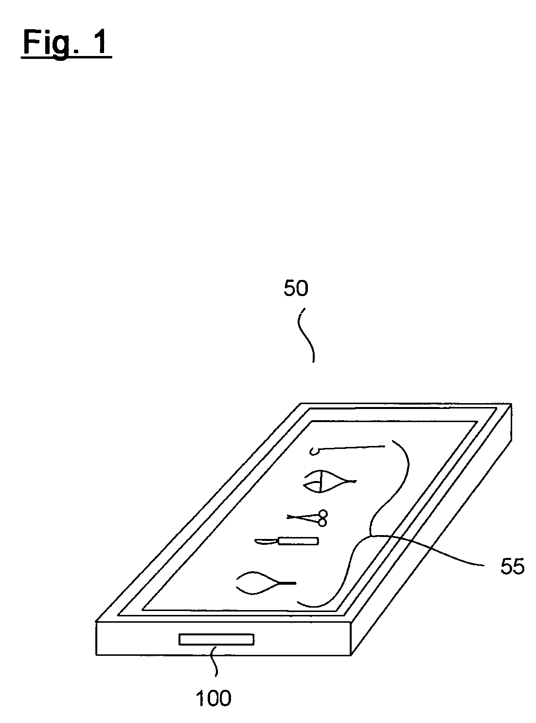
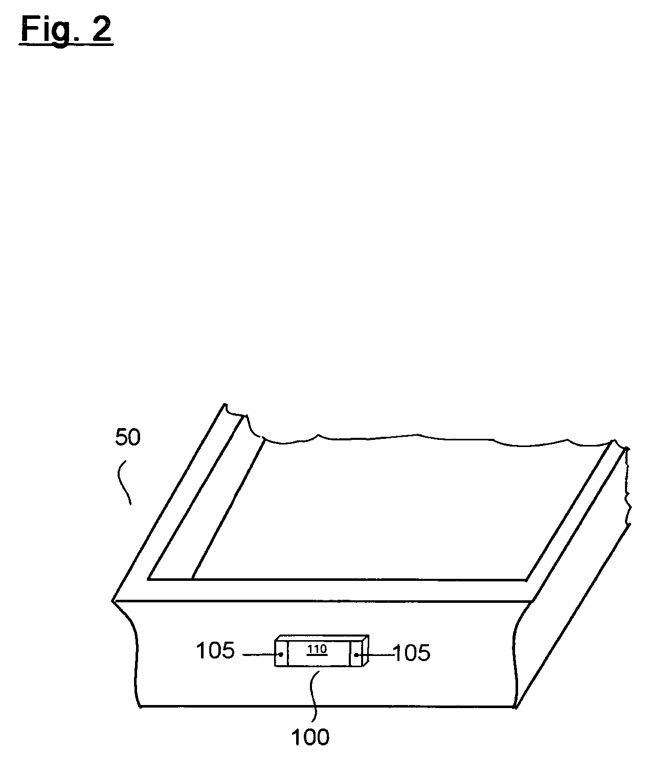
Surgical instrument tray RFID tag
a technology of radio frequency identification and instrument tray, which is applied in the field of radio frequency identification systems, can solve the problems of surgical instruments that eventually reach the end of their life cycle, various instruments on a given tray may become lost, and the existing methods for performing these necessary functions are overly reliant on costly human interpretation, so as to achieve the effect of losing readability and being convenient to us
- Summary
- Abstract
- Description
- Claims
- Application Information
AI Technical Summary
Benefits of technology
Problems solved by technology
Method used
Image

Examples
Embodiment Construction
[0036] The following description is intended to convey a thorough understanding of the embodiments described by providing a number of specific embodiments and details involving surgical instrument tray RFID tags and methods of manufacturing surgical instrument tray RFID tags. It is understood, however, that the present invention is not limited to these specific embodiments and details, which are exemplary only. It is further understood that one possessing ordinary skill in the art, in light of known systems and methods, would appreciate the use of the invention for its intended purposes and benefits in any number of alternative embodiments, depending upon specific design and other needs.
[0037] As used herein, the expressions “RFID tag” and “RFID transponder tag” will refer to any active or passive type of electronic data storage device, read-only or read and write, that is wirelessly activated in the presence of a radio frequency (RF) field, including any currently available induct...
PUM
 Abstract
Description
Claims
Application Information