
System and method for lighting control network recovery from master failure

a lighting control network and master failure technology, applied in the field of wireless lighting control network recovery of master failure, can solve the problems of affecting the reliability of lighting control networks, so as to improve system reliability and reduce the cost of additional memory.

Active Publication Date: 2006-11-02
SIGNIFY HLDG BV
View PDF12 Cites 132 Cited by
  • Summary
  • Abstract
  • Description
  • Claims
  • Application Information

AI Technical Summary

Benefits of technology

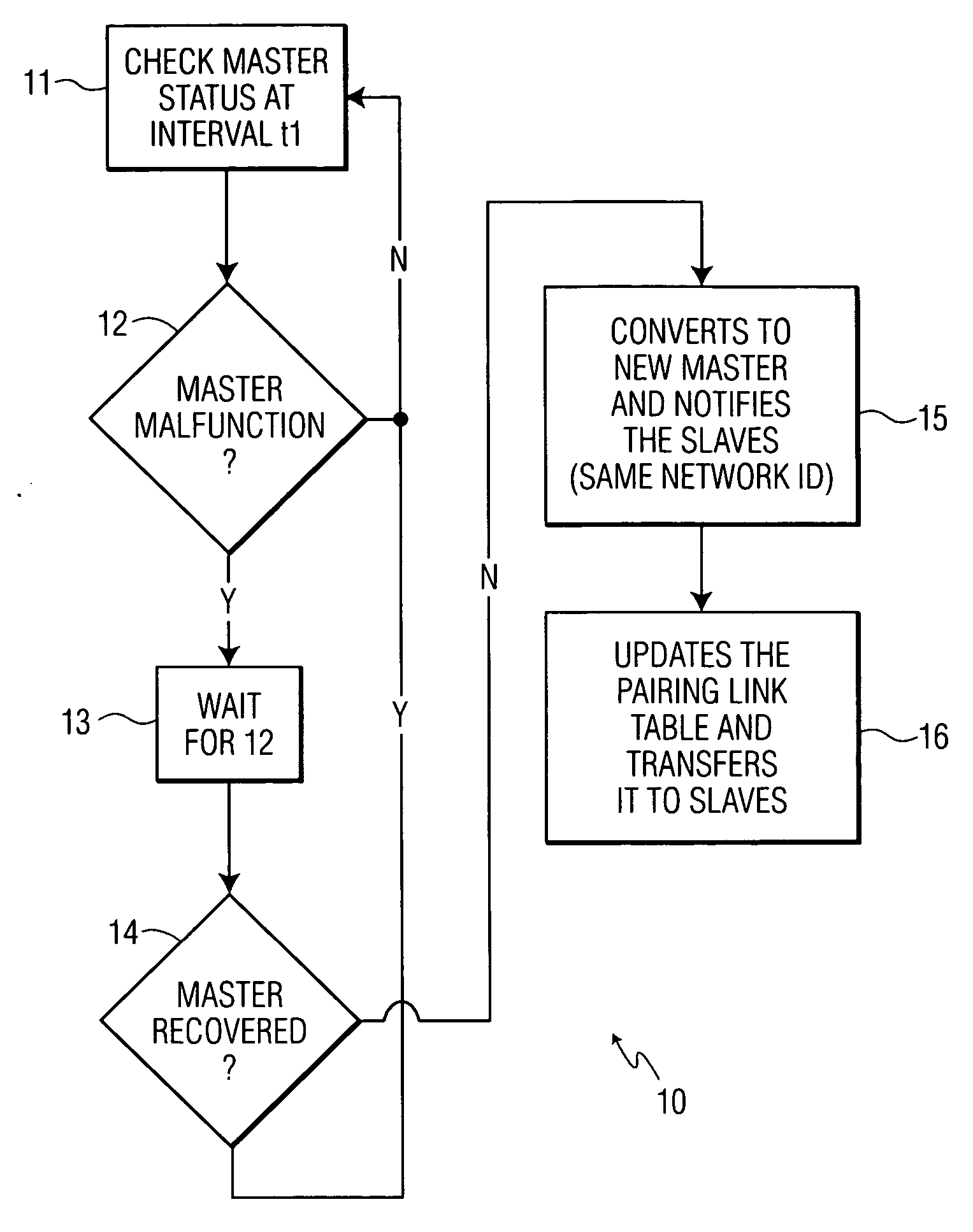
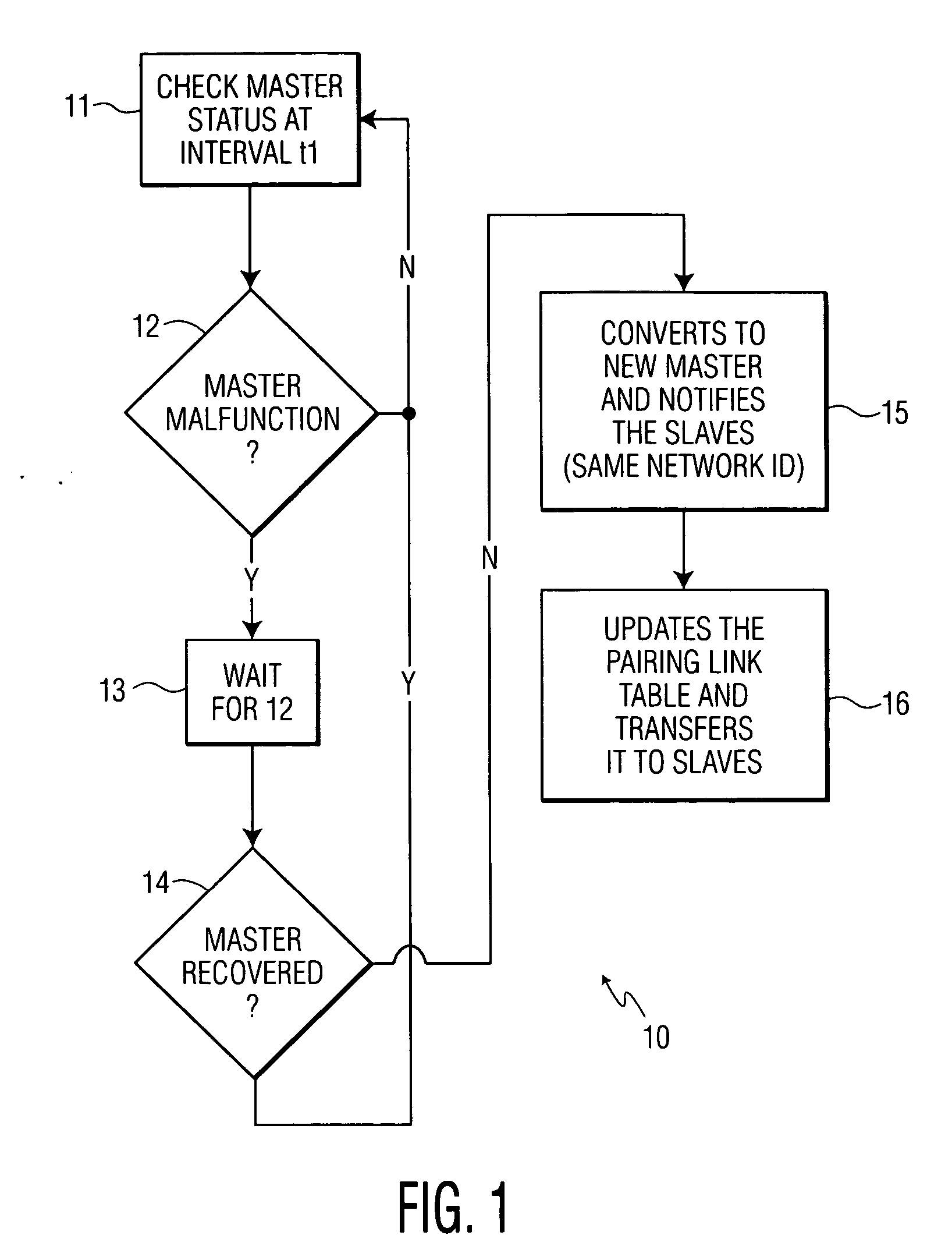
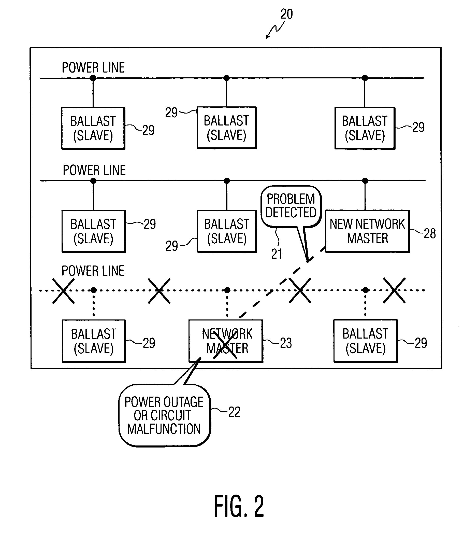
[0017] The present invention solves the problems associated with a single master, as discussed above, by providing multiple back-up masters in a master-slave orientated control network. The system and method of the present invention enhances system reliability without an extra device or costly circuitry. Each ballast in the network has the potential to be a master when needed. This means each device needs a little bit of extra memory to store the master program. In a digital ballast, the cost for additional memory is minimal.

Problems solved by technology

Being at a fixed location avoids problems a missing handheld remote control since all the network information is lost in such a case.
Sometimes the controller that happens to be installed on a different mains power line from the ballasts experiences a power outage.
Circuit malfunction: This includes circuit failures in the master control unit (MCU) or RF transceiver, and the temporary RF signal blockage / shielding or interference such that the communications between the devices are blocked.
Master Control Unit Failure: In a wireless network the master control unit represents a single point of failure.
That is, once the master fails, all link information kept only by the master is lost.
This also occurs because the master routes all the packets and the master fails.
However, this does not solve the problem of the master going completely dead.
However, it can be costly to provide an additional power supply to every control device.
In a master-slave networked system, due to the important role of the master, it is critical to make sure that there is always a master working properly at all times. If the controller fails due to a power outage (dead battery) or malfunction, the problem arises of to how to regain controls of the ballasts.

Method used


Image

  • System and method for lighting control network recovery from master failure
  • System and method for lighting control network recovery from master failure
  • System and method for lighting control network recovery from master failure

Examples


Embodiment Construction

[0024] The wireless lighting control network functions analogously to a wireless communication network. The lighting network itself is identified by a network ID, which is the essential information for communication among all the network nodes and there is a several layer communication protocol stack associated with every component of the wireless lighting network. After the network is established by the master and an enumeration of the lighting elements and pairing of enumerated lighting elements with keys are done, the master has all the pairing information stored in a pairing-link table in the protocol stack. Each pairing-link table entry specifies which ballast(s) reacts to which key and on which remote control. The master transfers this pairing-link table to all the slaves in the network. Every time the pairing-link table is changed, the master keeps all the slaves updated.

[0025] Master and slaves exchange status information at pre-determined intervals to make sure that the ma...


PUM


Abstract

The present invention provides a master-slave architecture for a radio frequency RF networked lighting control system having all slave elements (ballasts) configured as backups for a network master control unit. In the system and method of the present invention a slave element can become the network master network unit without reconfiguring the network and without any human intervention. Similarly, both a master and one or more slave elements may recover from a temporary outage without necessitating reconfiguration of the network and without any human intervention.

Description

BACKGROUND OF THE INVENTION [0001] 1. Field of the Invention [0002] This invention is related to recovering the ballast control in a wireless lighting control network when the main controller (master) fails. More particularly, this invention is related to a wireless lighting control network system and method in which all lighting ballasts act as backups for a network master control unit. Most particularly, this invention is related to a system and method for a master-slave architecture for a wireless lighting control network that include all lighting ballasts as backup for a network master control unit such that there is no need for reconfiguration of the network or human intervention when a master fails or functioning of the master or slave ballasts is interrupted. [0003] 2. Description of Related Art [0004] Traditional lighting has wall switches wired to the ballasts individually or in groups. If one of the switches fails, the ballasts that are controlled by other switches won't b...

Claims


Application Information

Patent Timeline
IPC IPC(8): G08B5/36H05B37/02
CPCH05B37/0272H05B47/19
Inventor WANG, LINGGIANNOPOULOS, DEMETRI J.
Owner SIGNIFY HLDG BV
Learn More