Compact, multi-element antenna and method

a multi-element, compact technology, applied in the field of antennas, can solve the problems of reducing the gain and efficiency of the antenna, affecting the attractiveness of the appearance, and generally not sufficiently compact basic dipole antenna b>10/b> to be used in portable electronic devices

Inactive Publication Date: 2006-11-02
VULCAN PORTALS
View PDF17 Cites 132 Cited by
  • Summary
  • Abstract
  • Description
  • Claims
  • Application Information

AI Technical Summary

Problems solved by technology

However, the basic dipole antenna 10 is generally not sufficiently compact to be useable in portable electronic devices such as PC's, PDA's and cellular telephones.
Placing the antenna and cover outside the housing undesirably increases the external dimensions of the electronic device, and it may adversely affect the attractiveness of its appearance.
A conductive housing surrounding the printed circuit board thus significantly reduces the gain and efficiency of the antenna.

Method used


Image

  • Compact, multi-element antenna and method
  • Compact, multi-element antenna and method
  • Compact, multi-element antenna and method

Examples


Embodiment Construction

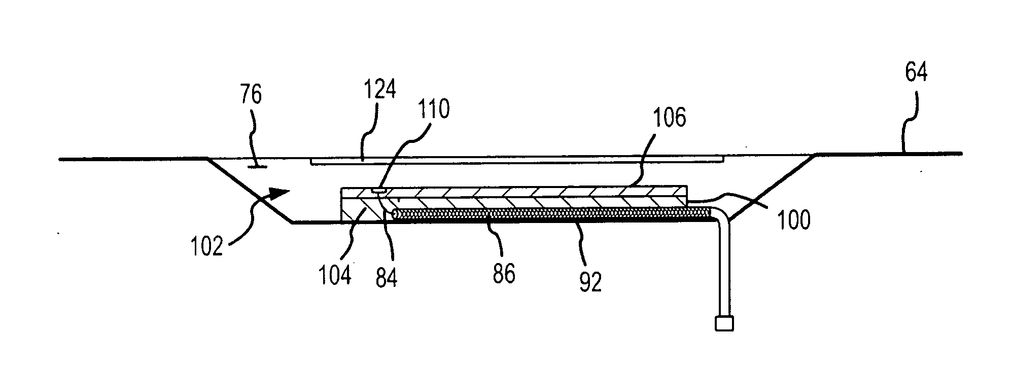
[0020] A handheld portable computer 60 using one example of an antenna according to the present invention is shown in FIG. 5. The computer 60 consists of a two-part clamshell case having a lower housing 64 to which a lid 66 is pivotally mounted through hinges 68. The lid 66 houses a display 70, which is visible on the inner surface of the lid 66. The lower housing 64 typically contains most of the circuitry (not shown) for the computer 60, and this circuitry is generally mounted on printed circuit boards (not shown). A keyboard 74 is mounted on the upper surface of the lower housing 64. The portable computer 60 also includes a wireless transceiver (not shown) mounted in the lower housing 64 to provide the computer with wireless communication capabilities.

[0021] In the handheld portable computer 60, both the lower housing 64 and the lid 66 are formed from sheets of a conductive metal such as magnesium. As a result, the wireless transceiver cannot use an internal antenna as is typica...


PUM


Abstract

An antenna is specially adapted for a portable electronic device, such as a hand-held computer or cell phone, having a conductive metal housing surrounding a radio transceiver. A rectangular recess is formed in one surface of the housing, and an elongated printed circuit board is placed along an inner wall of the housing. A coaxial cable coupled to the transceiver enters the housing, and an outer shield of the cable is connected to the inner wall of the housing along a substantial length of the cable. A center conductor of the cable is connected to a conductive layer of the printed circuit board. The recess is enclosed by a window that is substantially transparent to RF energy. RF energy radiated from the printed circuit board is capacitively coupled to a sheet of conductive material, and the RF energy is then radiated from the conductive sheet.

Description

FIELD OF THE INVENTION [0001] This invention relates to antennas, and, more particularly, an antenna that is suitable for use with a portable device having a conductive metal case in which the antenna is housed. BACKGROUND OF THE INVENTION [0002] A wide variety of portable devices are provided with wireless capabilities using either infra-red or radio transceivers. For example, portable personal computers and personal digital assistants (“PDA's”) may have IEEE-802.11 WiFi or “Wi-Fi” communication capabilities. Cellular telephones are another common example of portable devices using radio transceivers. In such devices, an antenna is required to transmit and receive radio signals. The most common types of antennas used in such devices are variations of a dipole antenna. In a basic dipole antenna 10 as shown in FIG. 1, a radio frequency (“RF”) signal is applied between two “legs”14, 16 of the dipole antenna. However, the basic dipole antenna 10 is generally not sufficiently compact to ...

Claims


Application Information

Patent Timeline
Patent Type & Authority Applications(United States)
IPC IPC(8): H01Q1/38H01Q1/24
CPCG06F1/1616H01Q9/0414H01Q1/243G06F1/1698
Inventor FLECK, ROD G.HILL, ROBERT J.
Owner VULCAN PORTALS
Why Eureka
Try Eureka