Cellular antenna and systems and methods therefor

Inactive Publication Date: 2006-11-02
COMMSCOPE TECH LLC
View PDF21 Cites 61 Cited by
  • Summary
  • Abstract
  • Description
  • Claims
  • Application Information

AI Technical Summary

Problems solved by technology

Systems for effecting mechanical adjustment of antenna beam azimuth

Method used


Image

  • Cellular antenna and systems and methods therefor
  • Cellular antenna and systems and methods therefor
  • Cellular antenna and systems and methods therefor

Examples


first embodiment

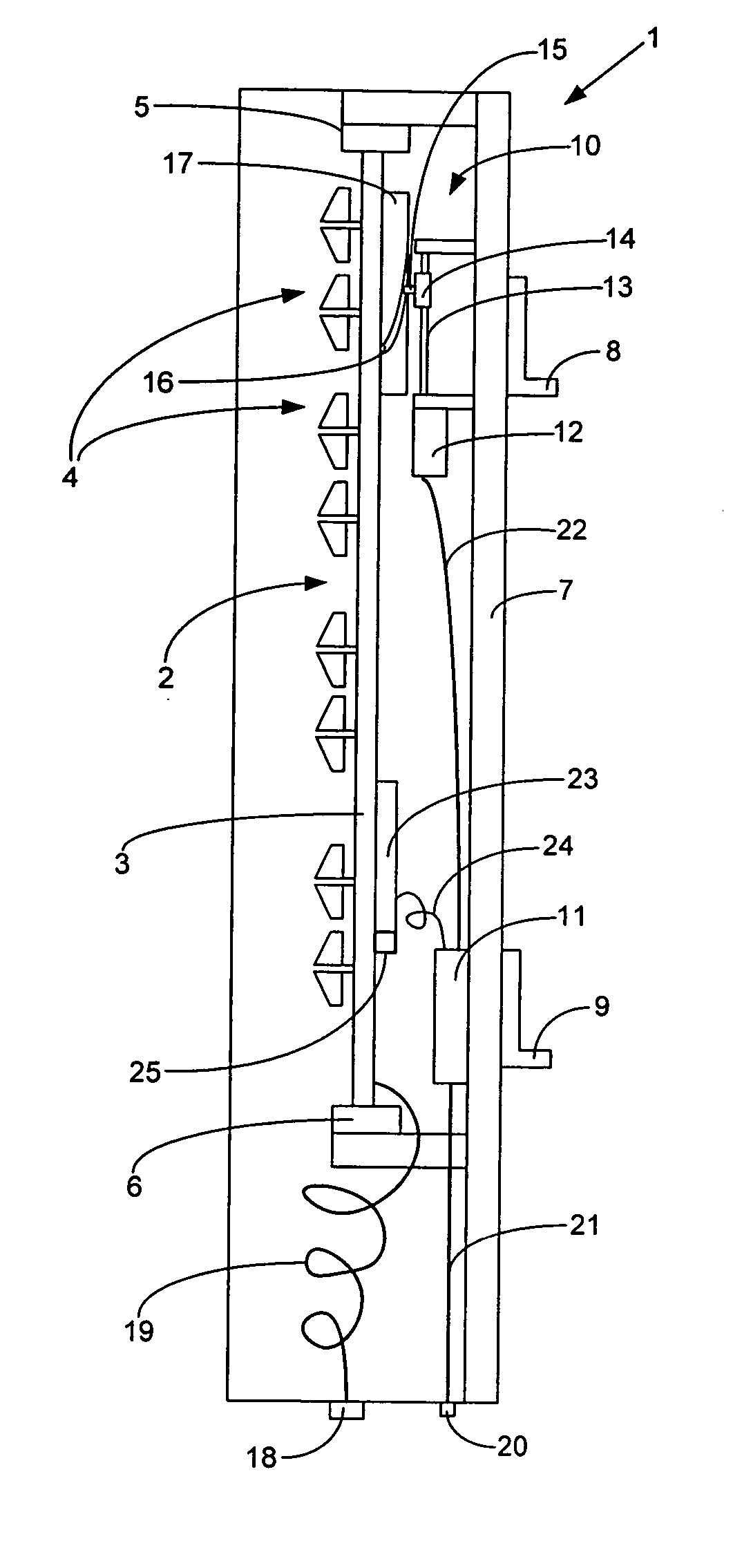
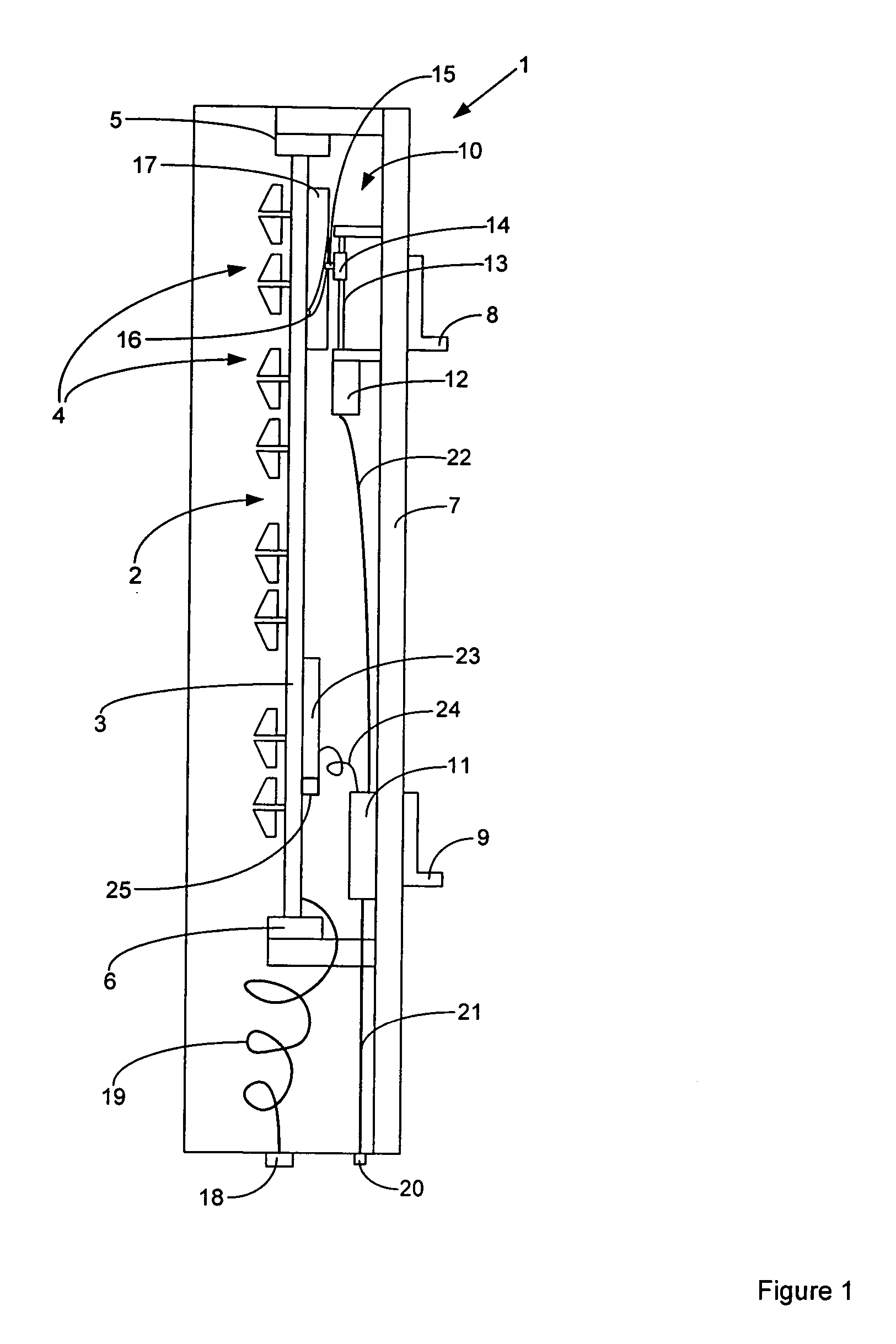
[0037]FIG. 1 shows a side view of a cellular antenna 1 according to a Antenna 1 includes an array antenna 2 having a reflector 3 and a plurality of radiating elements 4 (only some of which are indicated and the number of which may vary). Reflector 3 is rotatable about bearings 5 and 6 so that the array antenna 2 can rotate with respect to antenna support 7. Mounting brackets 8 and 9 allow the antenna to be mounted to a support structure such as a tower.

[0038] An azimuth position actuator 10 rotates array antenna 2 with respect to antenna support 7 in response to drive signals from actuator controller 11. Azimuth position actuator 10 includes a geared motor 12 driving a threaded shaft 13 which drives a nut 14 up and down as it rotates. Nut 14 has a pin 15 projecting therefrom which locates within a helical groove 16 in semi cylindrical guide 17. As pin 15 moves up and down guide 17 causes the array antenna 2 to rotate about its vertical axis to provide mechanical azimuth steering. I...

second embodiment

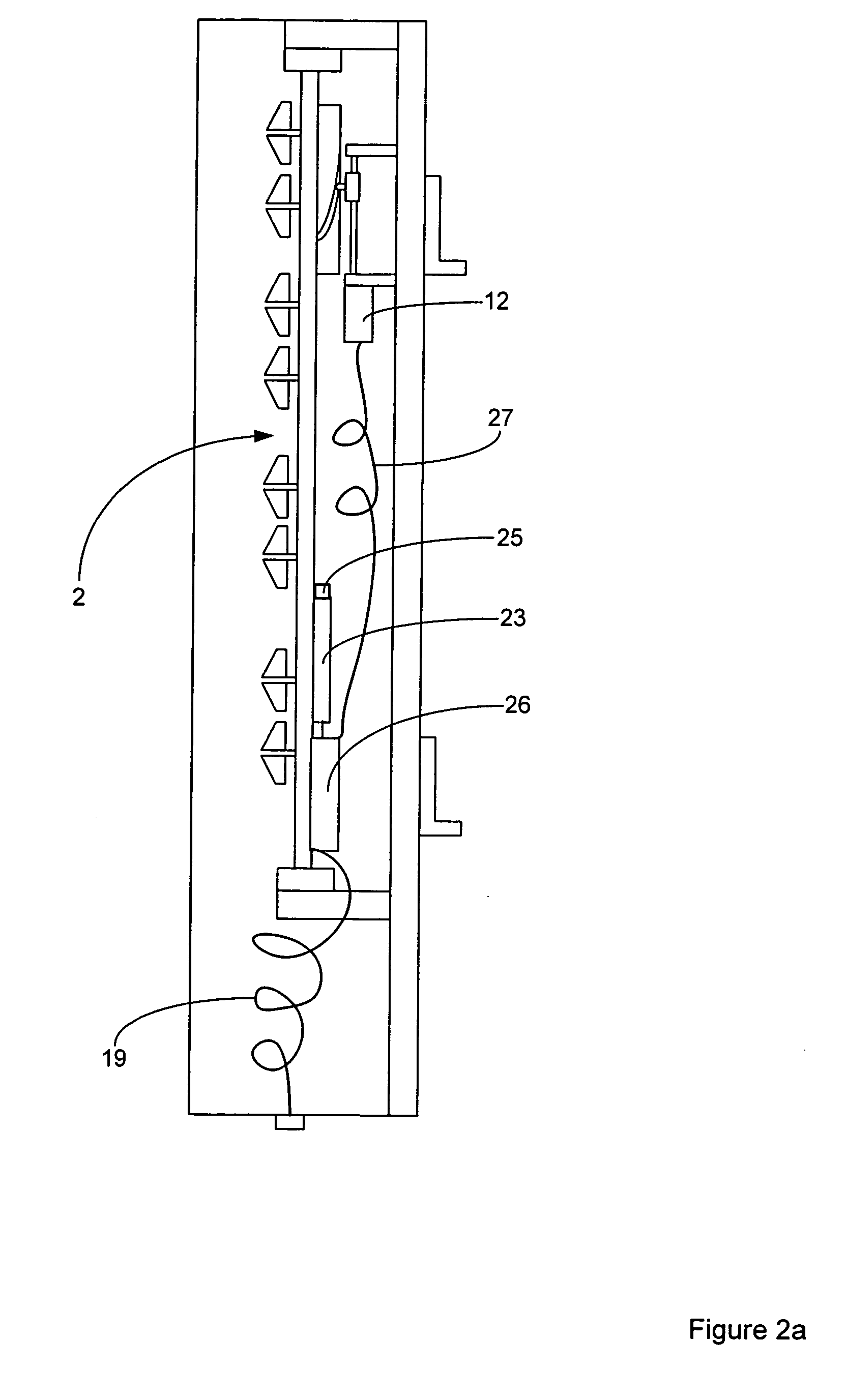
[0044]FIG. 2a shows a second embodiment in which all RF signals and control data are received over a single RF feed line. Like integers had been given like numbers to those shown in FIG. 1. In this embodiment RF feed line 19 supplies RF feed signals to antenna interface 26 which supplies RF signals to variable feed assembly 23 and extracts and supplies control data to actuator controller 23. As antenna interface 26 is mounted to reflector 3 a flexible control cable 27 is provided to azimuth motor 12. Antenna interface 26 may extract power supplied by an RF feed line to operate actuator controller 23 and it associated actuators. A DC bias voltage may be applied to the RF feed line at the base of a cellular base station tower and extracted by antenna interface 26 at the top of the tower. This arrangement has the advantage that only a single RF feed line need be connected to each antenna to provide both RF signals and control data.

[0045]FIG. 2b shows a variant of the embodiment shown i...


PUM


Abstract

There is provided a cellular antenna allowing mechanical azimuth adjustment in combination with adjustment of one or more other antenna attribute such as electrical down tilt, electrical beam width or electrical azimuth adjustment. An integrated control arrangement is provided which can utilise either serial, wireless or RF feed lines to convey communications. A multiband embodiment provides azimuth adjustment for both bands by utilising mechanical and electrical azimuth adjustment. Systems incorporating such antennas and methods of controlling them are also provided.

Description

CROSS-REFERENCE TO RELATED APPLICATIONS [0001] This is a continuation-in-part of and claims the benefit of priority from application Ser. No. 10 / 312,979, filed Jul. 10, 2001(PCT Filing Date), entitled Cellular Antenna, and currently pending.FIELD OF THE INVENTION [0002] This invention relates to a cellular antenna and systems incorporating the antenna as well as to methods of controlling the antenna. More particularly, although not exclusively, there is disclosed an antenna providing mechanical azimuth adjustment of the beam of the antenna in combination with adjustment with other antenna attributes. BACKGROUND OF THE INVENTION [0003] The applicant's prior application US2004 / 0038714A1 (Rhodes), the disclosure of which is incorporated by reference, discloses an antenna system providing remote electrical beam adjustment for down tilt, beam width and azimuth. [0004] Systems for effecting mechanical adjustment of antenna beam azimuth are known but have not been well integrated into a ce...

Claims


Application Information

Patent Timeline
IPC IPC(8): H01Q21/00
CPCH01P1/18H01Q1/246H01Q3/06H01Q3/20H01Q3/24H01Q21/28H01Q3/32H01Q21/06H01Q21/061H01Q21/22H01Q21/26H01Q3/26
Inventor ELLIOT, ROBERT DOUGLASZIMMERMAN, MARTIN L.LINEHAN, KEVIN ELDONGRAHAM, PETER BRUCEMAILANDT, PETERMEYER, LOUIS JOHNSORELLS, PHILIPGRAY, ANDREW THOMASYANG, CHING-SHUN
Owner COMMSCOPE TECH LLC
Why Eureka
Try Eureka