Display device
a display screen and display technology, applied in static indicating devices, substation equipment, instruments, etc., can solve the problems of insufficient fundamental solution, deterioration of visibility, and lowering image quality under indoor fluorescent light, so as to ensure visibility, excellent visibility, and excellent visibility. the effect of information displayed on the display screen
- Summary
- Abstract
- Description
- Claims
- Application Information
AI Technical Summary
Benefits of technology
Problems solved by technology
Method used
Image
Examples
embodiment 1
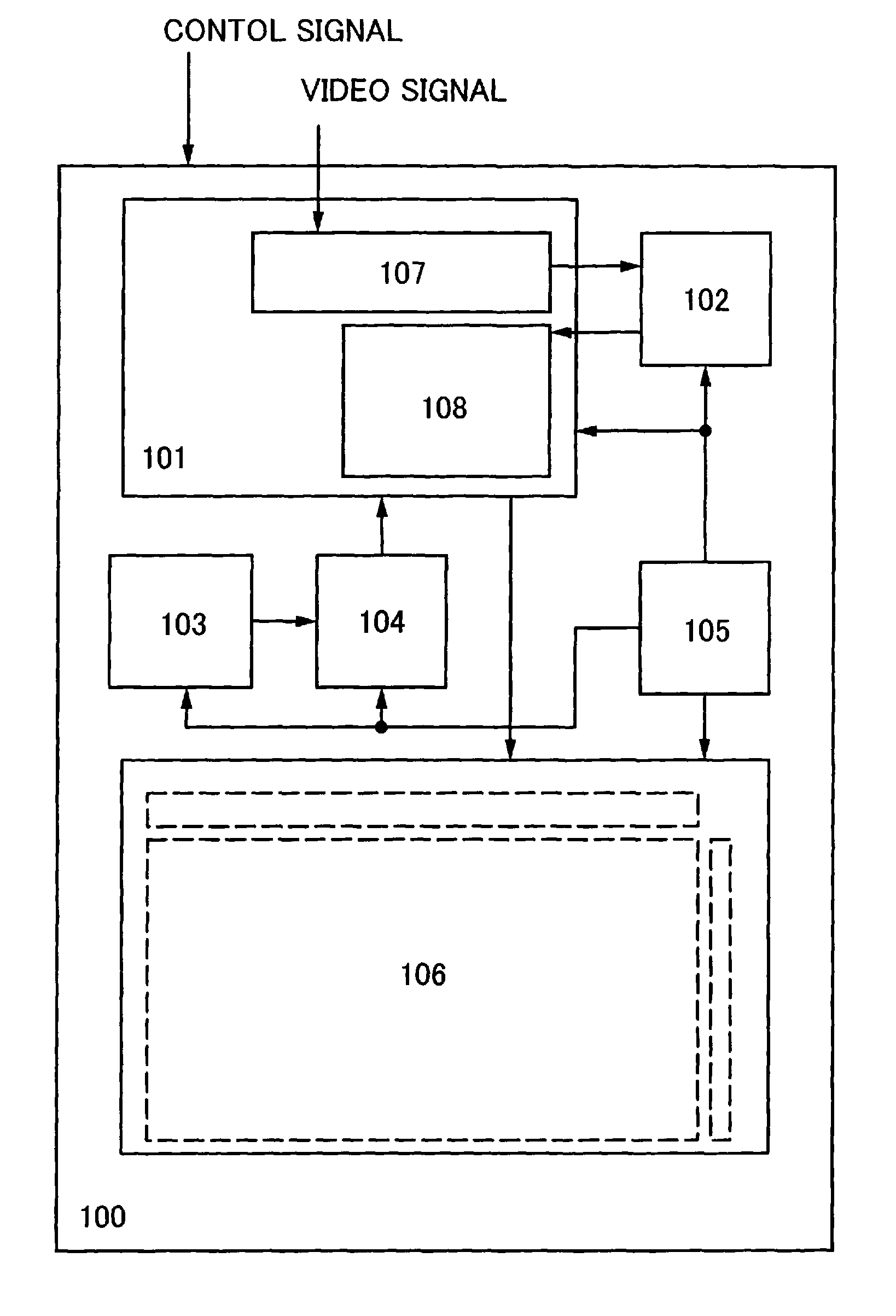
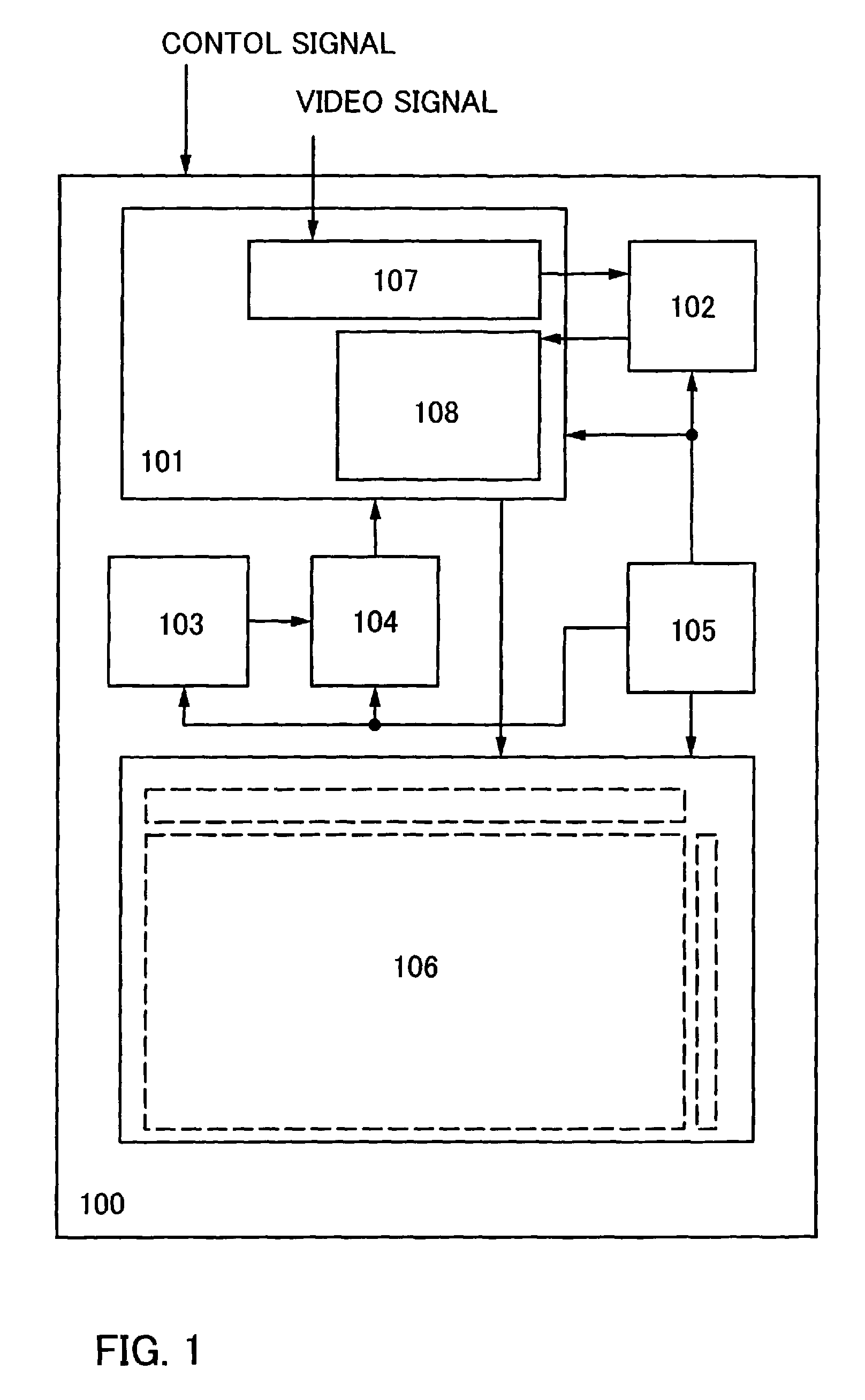
[0042] An embodiment mode of the invention is shown in FIG. 1. FIG. 1 shows a block diagram of a display device of the invention. The display device 100 includes controller 101, a memory 102, a light sensor 103, an amplifier 104, a power supply 105 and a display panel 106.
[0043] The controller 101 generates a signal necessary for driving the display panel 106, based on a control signal and a video signal inputted from outside and a light sensor signal supplied from the amplifier 104. Then, it supplies these signals to the display panel 106. The memory 102 is used mainly for storing a video signal temporarily. In addition, the memory 102 is also used for storing information other than a video signal. The light sensor 103 detects external light (external light which the display device 100 receives). The output is supplied to the amplifier 104. The amplifier 104 amplifies an electrical signal outputted by the light sensor 103, and supplies the amplified electrical signal to the contro...
embodiment mode 2
[0061] A configuration example of a pixel of the display device shown in Embodiment Mode 1 will be shown. FIGS. 3A and 3B shows a pixel example of a display device which can operate with a time grayscale method. The pixel shown in FIGS. 3A and 3B is constituted by a thin film transistor (hereinafter also referred to as TFT). FIGS. 3A and 3B show a pixel which drives a light-emitting element 303 with time grayscale. This pixel is constituted by the light-emitting element 303, a driving TFT 302, a retention volume 304 and a switching TFT 301. A gate of the switching TFT 301 is connected to a gate signal line G1, and when the gate signal line G1 is high, it becomes on and the data of a source signal line S1 is written on the retention volume 304 and a gate of the driving TFT 302. When the driving TFT 302 becomes on, a current from a power line V1 flows to the light-emitting element 303, via the driving TFT 302. This condition is maintained till the next writing is performed.
[0062]FIG....
embodiment mode 3
[0063] As for the display device shown in Embodiment Mode 2, an example of a system to form an image of which light and dark of signals are inverted, as described in Embodiment Mode 1, is shown in FIG. 4. In this example, a digital video signal of 4 bits is sub-frame-converted, but not limited especially to 4 bits. The operation will be described hereinafter. First, a control circuit 402 inputs a digital video signal to a first memory 404 via a switch 403. When the data of a first frame is all inputted to the first memory 404, the switch 403 is switched to a second memory 405, and a digital video signal of a second frame is written. By this means, a combination of a white background image and a black display image, or a combination of a black background image and a white display image can be displayed. The output of a picture signal selection switch 406 is inputted to a switch 407, and it can be selected whether a signal of the picture signal selection switch 406 is inputted without...
PUM
 Abstract
Description
Claims
Application Information
 - R&D
- Intellectual Property
- Life Sciences
- Materials
- Tech Scout
- Unparalleled Data Quality
- Higher Quality Content
- 60% Fewer Hallucinations
Browse by: Latest US Patents, China's latest patents, Technical Efficacy Thesaurus, Application Domain, Technology Topic, Popular Technical Reports.
© 2025 PatSnap. All rights reserved.Legal|Privacy policy|Modern Slavery Act Transparency Statement|Sitemap|About US| Contact US: help@patsnap.com


