Liquid container, liquid supply system and printing device using liquid container, and circuit board for liquid container

a technology for liquid containers and circuit boards, which is applied in printing, other printing apparatuses, etc., can solve the problems of destroying not only the information stored in the memory but also the memory in itself, and the ink cartridges have the disadvantage of a tremendous increase in manufacturing costs and complication, and the printing operation will be hindered

Active Publication Date: 2006-11-02
CANON KK
View PDF47 Cites 67 Cited by
  • Summary
  • Abstract
  • Description
  • Claims
  • Application Information

AI Technical Summary

Benefits of technology

[0069] Furthermore, according to the printing apparatus and a liquid container according to the present invention, it is poss

Problems solved by technology

On the contrary, in the case of using different types of the ink alternately in the single printing apparatus, the following obstacle may arise when the printing apparatus is particularly configured to allow attachment of a plurality of ink cartridges to a single ink jet head including a plurality of ejection portions.
When such an obstacle arises, a printing operation will be hindered.
In this case, however, the ink cartridges have disadvantages of a tremendous increase in manufacturing costs and complication to store and manage the ink cartridges having the different shapes.
For this reason, if the ink tank is detached from the printing apparatus body during access to the memory and the communication line is suddenly shut down, there is a risk of destruction of not only the information stored in the memory but also the memory in itself depending on the type or the processes of the memory element.
In this way, along with the increase in the opportunities

Method used


Image

  • Liquid container, liquid supply system and printing device using liquid container, and circuit board for liquid container
  • Liquid container, liquid supply system and printing device using liquid container, and circuit board for liquid container
  • Liquid container, liquid supply system and printing device using liquid container, and circuit board for liquid container

Examples


first embodiment

[0121]FIG. 6 is a perspective view showing an example of a printing head unit configured to realize attachment and detachment of the ink tanks according to the Meanwhile, FIGS. 7A, 7B, and 7C are views for explaining an operation to attach the ink tanks to the printing head unit.

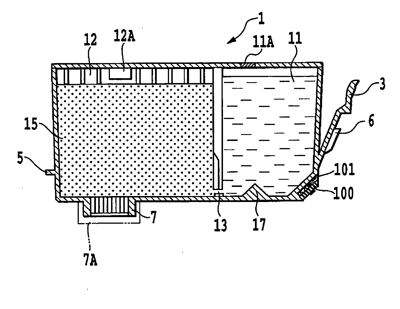
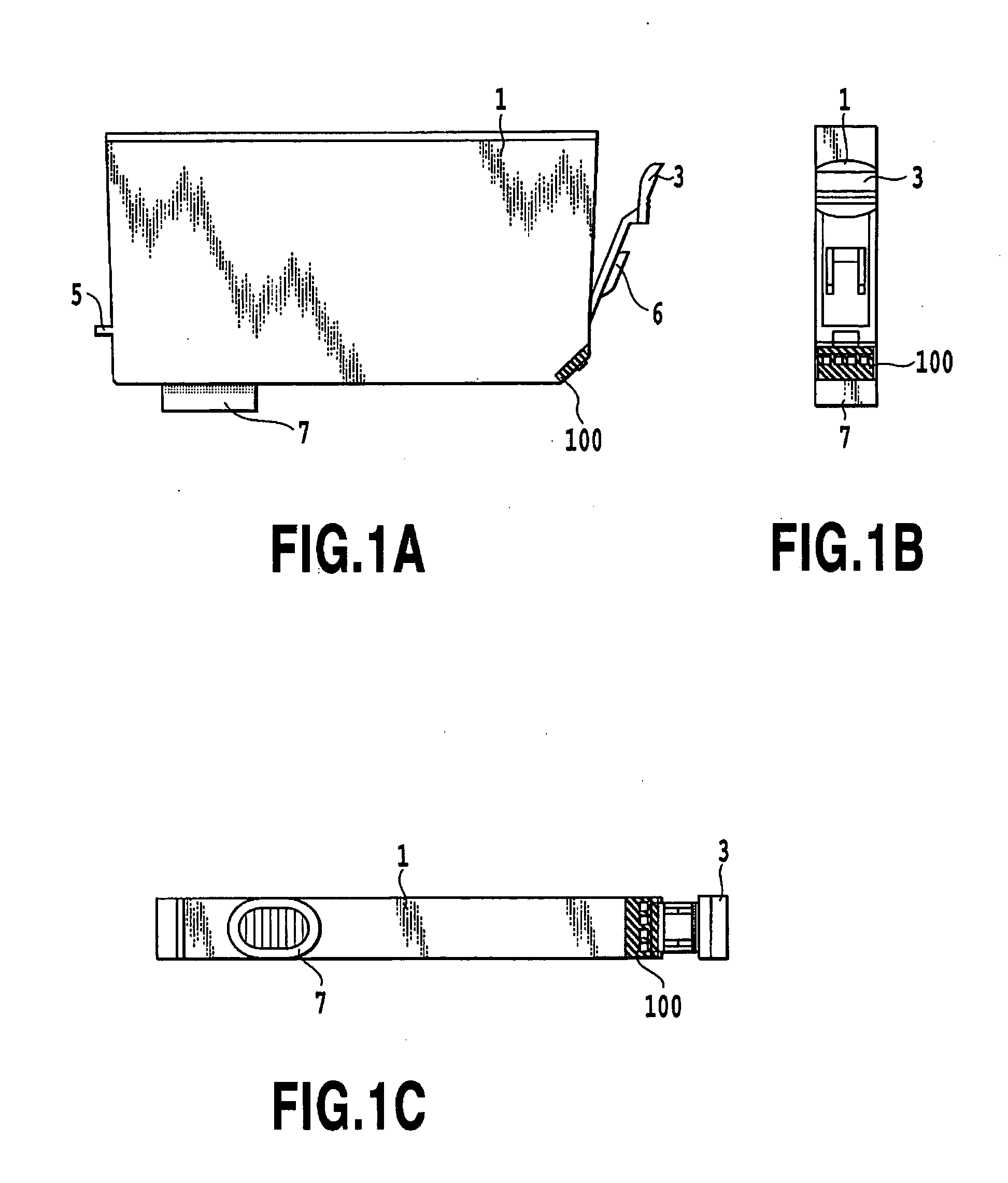
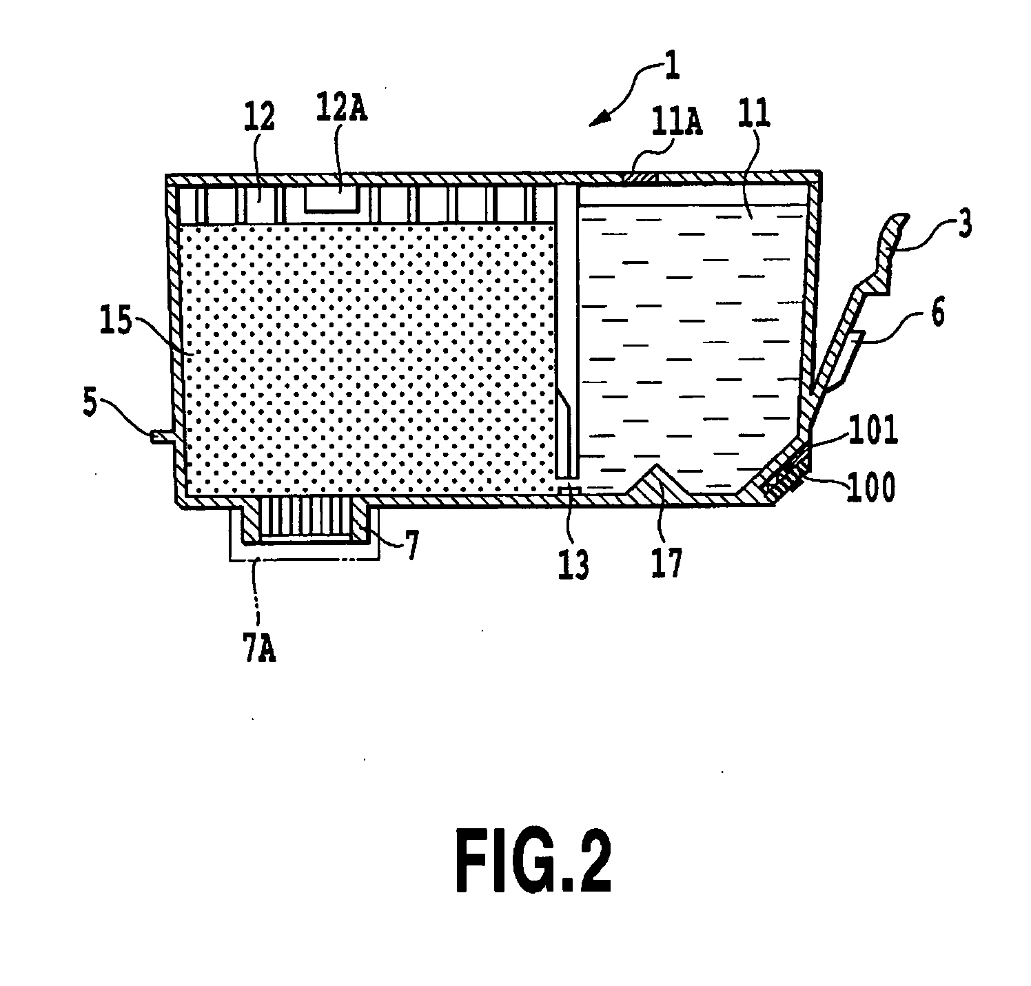
[0122] The printing head unit 105 generally includes the holder 150 for detachably holding a plurality (4 pieces in the drawing) of ink tanks, and the printing head 105′ (not shown in FIG. 6) to be disposed on a bottom face side. Here, an ink inlet port 107 on the printing head positioned at the bottom of the holder is connected to the ink supply port 7 on the ink tank by attaching each of the ink tanks to the holder 150. In this way, an ink communicating path is formed between the holder and the ink tank.

[0123] A component provided with an electrothermal transducer element in a fluid path constituting a nozzle can be used in the printing head 105′. This component is configured to apply thermal energy to t...

second embodiment

[0166] The timing for allowing a storage area (the register) of the volatile memory 103D to retain the information temporarily may be configured as follows. For instance, a command for transferring desired information is transmitted from the control circuit 300 on the body to the input and output control circuit 103A as appropriate (when opening the cover of the printing apparatus, for example), and the command can be used as a trigger. Alternatively, as shown in the drawing, timing generated by a power-on-reset circuit (POR) 103E that responds to the time when the device is turned on is used for generating a trigger for causing the input and out put control circuit 103A to transfer the desired information from a non-volatile area to a volatile area in conformity therewith. The latter example will be described in detail in a

[0167] Here, when the information supposed to be stored temporarily is gathered in a specific address in the non-volatile memory 103B, it is possible to latch th...

second embodiment (

3. Second Embodiment (FIGS. 25 to 27)

[0216] Destruction of the content stored in the memory element and the memory element in itself due to hot-swap can be effectively prevented by the above-described embodiments. Moreover, the number of memory access can be reduced even in the case of using a non-volatile memory which has a limitation in the number of access. Accordingly, it is possible to extend the lifetime of the non-volatile memory and thereby to utilize reliable information for a long time period.

[0217] The next embodiment intends to further reduce the number of access to a non-volatile memory while utilizing the advantages attributed to the basic configuration of the first embodiment. Moreover, this embodiment is configured to read ink residual quantity at the time of attaching an ink tank and to perform display in response thereto. In addition, this embodiment is configured to recover data in the event of destruction of the data such as the ink residual quantity stored in a...


PUM


Abstract

An ink tank detachably mounted on a printer includes a non-volatile memory and a LED for executing a process in response to a condition of the tank such as ink residual quantity by transmitting information stored in the memory to a printer, and informing the condition of the ink by use of the LED. Further, the content stored in the memory is prevented from being destroyed, and the LED can perform light emission until immediately before detachment and thus contribute to improvement in workability of a user. A volatile memory element is provided in addition to the non-volatile memory. When a user can detach the tank, condition information on the ink tank retained by the non-volatile memory is transferred to the volatile memory in advance. When it is possible to detach the tank, control for turning the LED on and off is achieved by accessing only to the volatile memory.

Description

BACKGROUND OF THE INVENTION [0001] 1. Field of the Invention [0002] The present invention relates to a liquid container. More specifically, the present invention relates to a liquid container used in a configuration to detect information on a state of the liquid container (such as information on residual quantity in an ink tank used for ink jet printing), by use of light emitting means such as a light emitting diode (LED). The present invention also relates to a liquid container system and a printing apparatus using the liquid container, and to a circuit board for the liquid container. [0003] 2. Description of the Related Art [0004] Performances of ink jet heads are dramatically improved in recent years along with increasing demands for higher resolution and higher image quality printing. Specifically, printing speed and printing throughput are improved by increasing the number of ejection ports and energy generating elements in a printing head or by increasing the number of energy ...

Claims


Application Information

Patent Timeline
IPC IPC(8): B41J2/175
CPCB41J2/17509B41J2/17513B41J2/17566B41J2/17546B41J2/1752
Inventor HAYASAKI, KIMIYUKIWATANABE, KENJIROHATASA, NOBUYUKIYAMAZAKI, TATSUHIKO
Owner CANON KK
Why Eureka
Try Eureka