
Method and apparatus for recording data on optical recording medium

a technology of optical recording medium and optical recording medium, which is applied in the direction of digital signal error detection/correction, instruments, television systems, etc., can solve the problems of degrading recording/reproducing characteristics, prolonging the mark length, and affecting the quality of the recording. , to achieve the effect of preventing degradation

Inactive Publication Date: 2006-11-02
SAMSUNG ELECTRONICS CO LTD
View PDF31 Cites 5 Cited by
  • Summary
  • Abstract
  • Description
  • Claims
  • Application Information

AI Technical Summary

Benefits of technology

[0012] In accordance with a first aspect of the present invention, there is provided a method and apparatus to record data using a recording waveform which is capable of preventing leading and trailing edges of a mark from being distorted and preventing degradation caused by repeated recording.
[0013] According to a second aspect of the present invention, there is provided a method and apparatus to record data using a recording waveform having an erase pattern which is capable of improving a shape of a mark.

Problems solved by technology

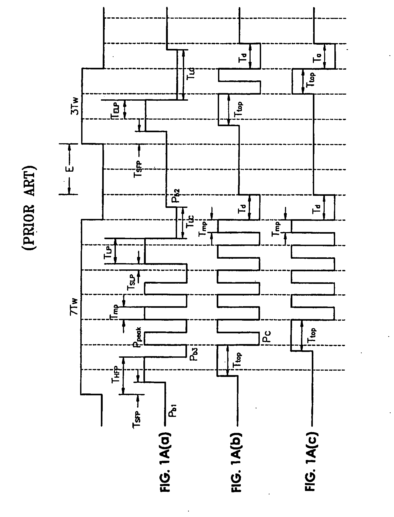
A relatively long length of the mark further degrades recording / reproducing characteristics due to thermal accumulation.
As a result, the recording / reproducing characteristics are much more degraded when thermal interference between pulses constituting the recording waveform is increased.
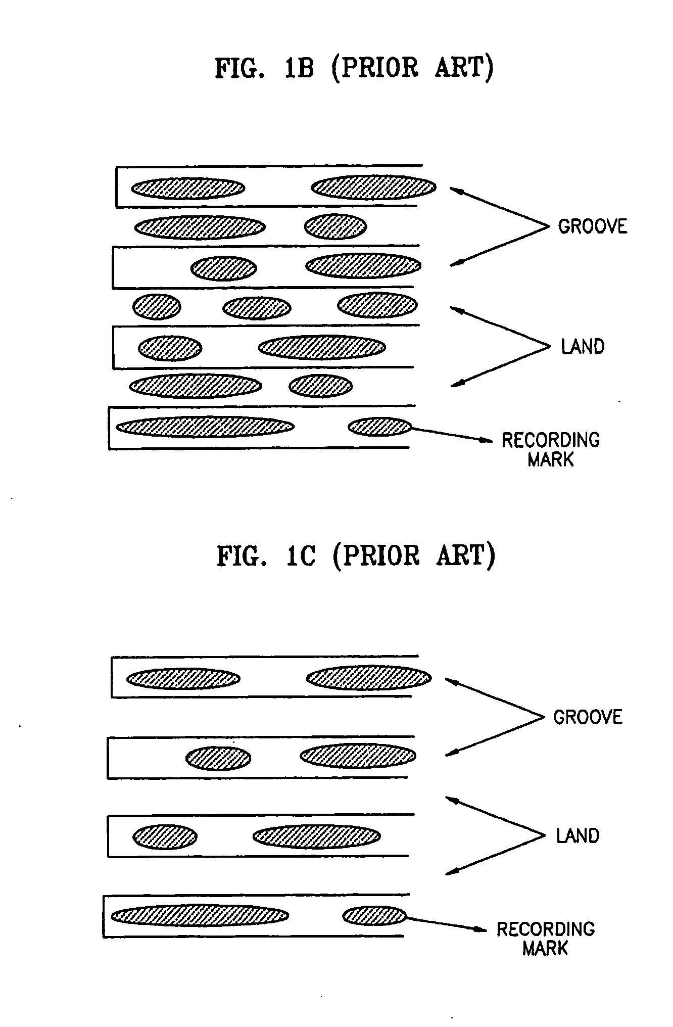
However, in the method shown in FIG. 1C, previously-formed marks may also be affected by applying too much heat when forming predetermined marks.
The use of different recording waveforms for different discs becomes a problem when manufacturing drives to record the data on different types of discs because drives that can read different types of discs should realize various recording waveforms, which increases costs.

Method used


Image

  • Method and apparatus for recording data on optical recording medium
  • Method and apparatus for recording data on optical recording medium
  • Method and apparatus for recording data on optical recording medium

Examples


Embodiment Construction

[0047] Reference will now be made in detail to the embodiments of the present invention, examples of which are illustrated in the accompanying drawings, wherein like reference numerals refer to like elements throughout. The embodiments are described below in order to explain the present invention by referring to the figures.

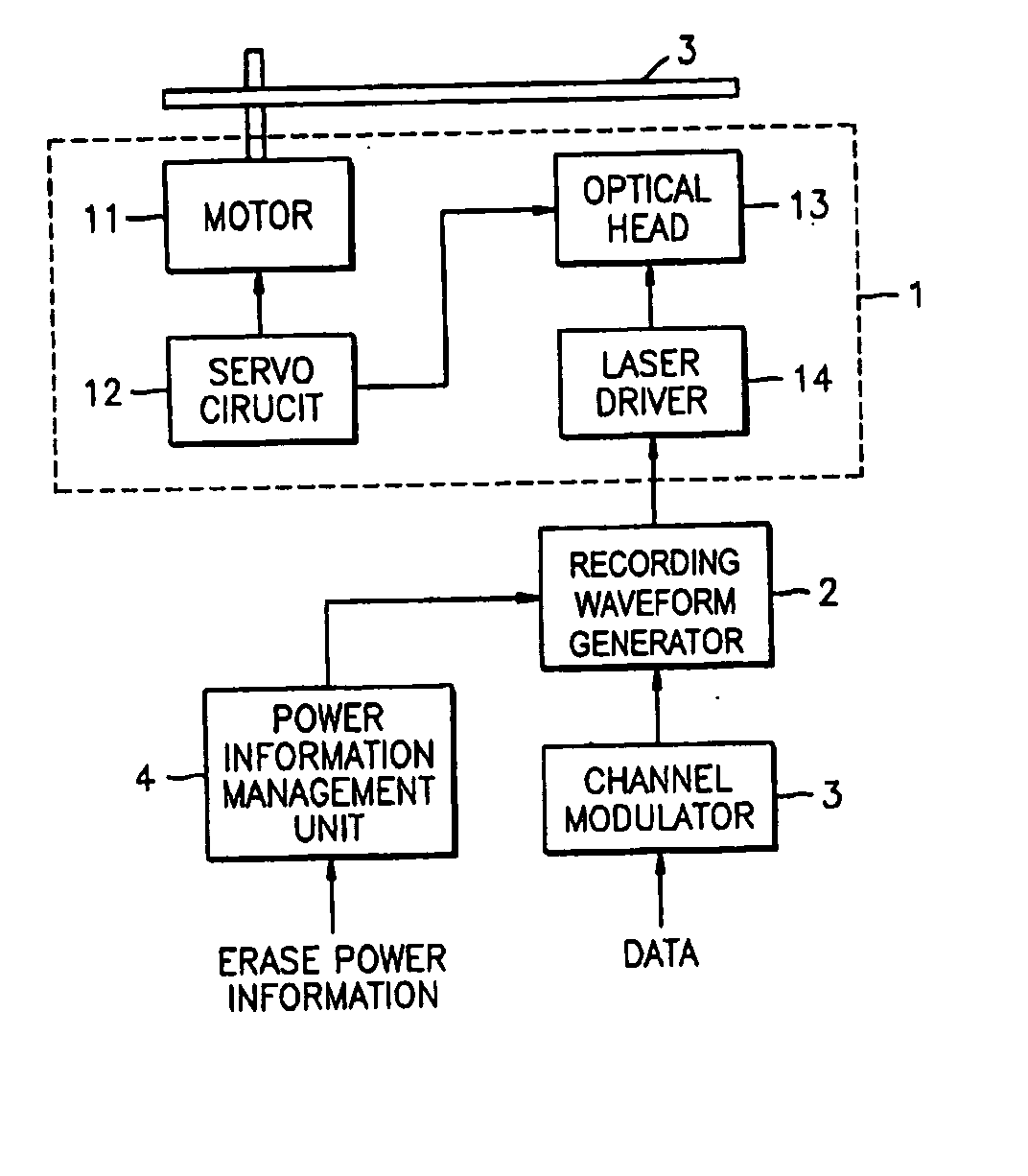
[0048]FIGS. 2A and 2B are block diagrams of recording apparatuses, according to aspects of the present invention. Referring to FIG. 2A, the recording apparatus, which forms a mark or a space to record data on an optical recording medium 200, includes a pickup unit 1, a recording waveform generator 2, and a channel modulator 3.

[0049] The channel modulator 3 modulates input data to a channel bit sequence. The recording waveform generator 2 is supplied with information about the channel bit sequence and erase powers Pb1 and Pb2 and generates a recording waveform to record the channel bit sequence. The generated recording waveform includes an erase pattern having e...


PUM


Abstract

A method and apparatus to record data on an optical recording medium include generating a recording waveform having an erase pattern comprising a multi-pulse having a high level which is higher than an erase power level and a low level which is lower than the erase power level. A power level of a leading one of the multi-pulse of the erase pattern and a power level between an end of the erase pattern and a start point of a leading pulse of a recording pattern are controlled to be the low level and the high level, respectively, the high level and the high level, respectively, the high level and the low level, respectively, or the low level and the low level, respectively.

Description

CROSS-REFERENCE TO RELATED APPLICATIONS [0001] This application is a continuation application of U.S. patent application Ser. No. 10 / 372,675, filed Feb. 25, 2003, now pending, which is based upon and claims priority of Korean Patent Application No. 2002-9999 filed Feb. 25, 2002 in the Korean Intellectual Property Office, the disclosure of which is incorporated herein in its entirety by reference, and U.S. Provisional Application No. 60 / 373,378 filed in the United States Patent and Trademark Office on Feb. 25, 2003, the disclosures of which are incorporated herein by reference.BACKGROUND OF THE INVENTION [0002] 1. Field of the Invention [0003] The present invention relates to a method and apparatus to record data on an optical recording medium, and more particularly, to a method and apparatus to record digital data by forming a mark on an optical disc. [0004] 2. Description of the Related Art [0005] When recording data on an optical recording medium such as an optical disc, a mark is...

Claims


Application Information

Patent Timeline
IPC IPC(8): G11B7/0045G11B7/0055
CPCG11B7/00454G11B7/00557G11B7/00456
Inventor AHN, YONG-JINPARK, IN-SIKLEE, KYUNG-GEUNYANG, CHANG-JINOTSUKA, TATSUHIROKIM, SEONG-SUEKO, JUNG-WANYOON, DU-SEOP
Owner SAMSUNG ELECTRONICS CO LTD
Learn More