Optical fiber twisting apparatus, method of manufacturing optical fiber, and optical fiber

Active Publication Date: 2006-11-02
THE FUJIKURA CABLE WORKS LTD
View PDF9 Cites 1 Cited by
  • Summary
  • Abstract
  • Description
  • Claims
  • Application Information

AI Technical Summary

Benefits of technology

[0013] According to illustrative, non-limiting embodiments, it is possible to prevent line distortion occurring in an optical fiber undergoing a drawing process, and it is possible to consistently coat a bare optical fiber, and to prevent damaging the coated portion of an optical fiber where the optical fiber twisting roller makes contact. It is also possible to prevent an increase in attenuation of an optical fiber caused by delamination of the coated portion of the optical fiber, even when the optical fiber is installed in a low temperature environment.

Problems solved by technology

However, if the contact angle is increased, or if a large diameter optical fiber twisting roller is used, then due to the effects of the accuracy, assembly tolerances, etc. of the optical fiber twisting roller, when the optical fiber twisting roller is being swung, the pressing force of the optical fiber twisting roller on the coated portion of the optical fiber changes which results in a non-uniform force being applied to the optical fiber during the drawing process.
Consequently, problems arise such as irregular movement of the optical fiber rolling over the optical fiber twisting roller, and line distortion occurring such as the optical fiber moving to the left and right over the optical fiber twisting roller, so that consistent coating of the optical fiber with the primary coated portion and the secondary coated portion is no longer possible.
Moreover, when the optical fiber twisting roller is being swung in order to impart a twist to the optical fiber, damage is caused to the coated portion of the optical fiber where the optical fiber twisting roller makes contact due to the effects noted above.

Method used


Image

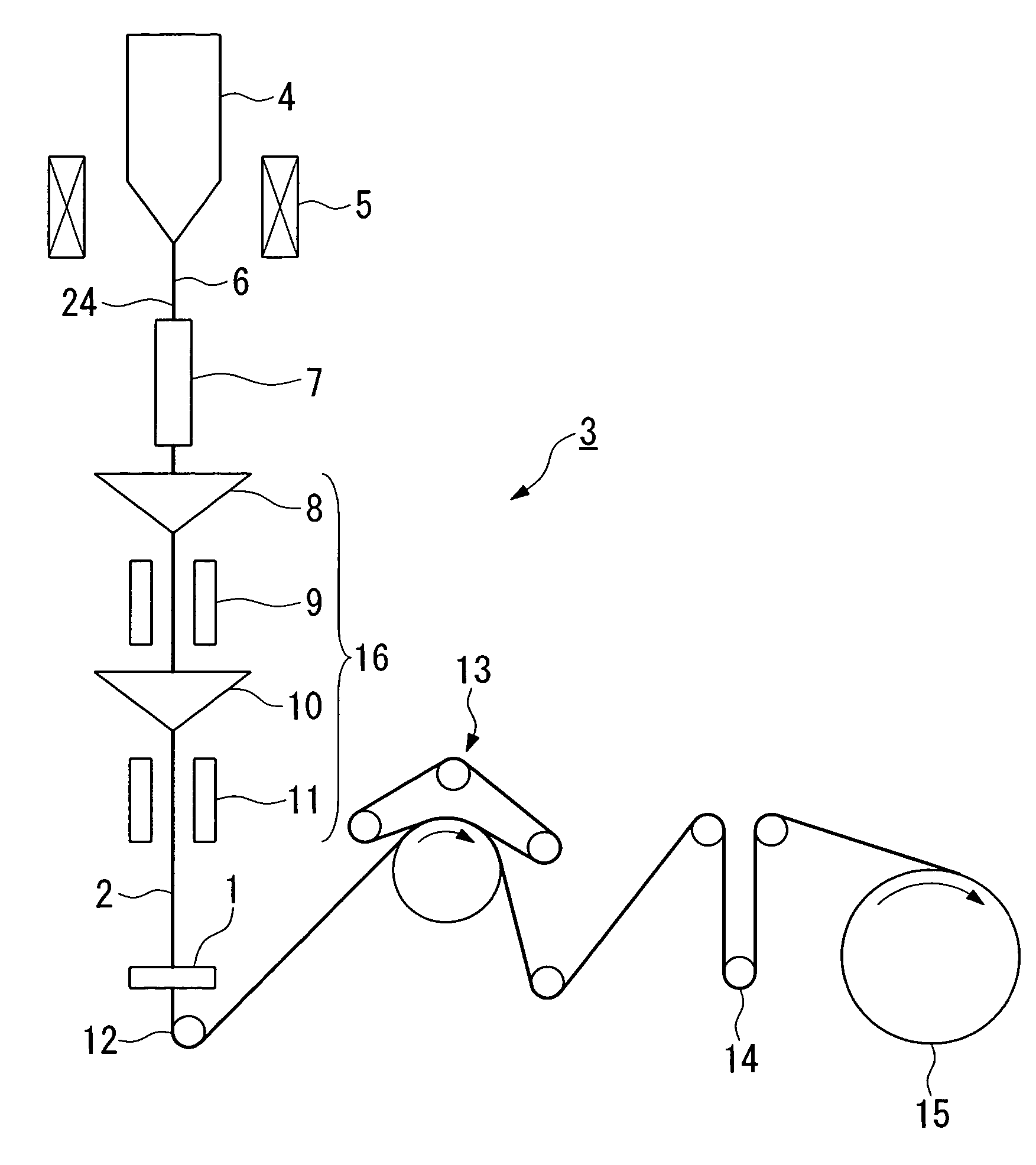
  • Optical fiber twisting apparatus, method of manufacturing optical fiber, and optical fiber
  • Optical fiber twisting apparatus, method of manufacturing optical fiber, and optical fiber
  • Optical fiber twisting apparatus, method of manufacturing optical fiber, and optical fiber

Examples


example 1

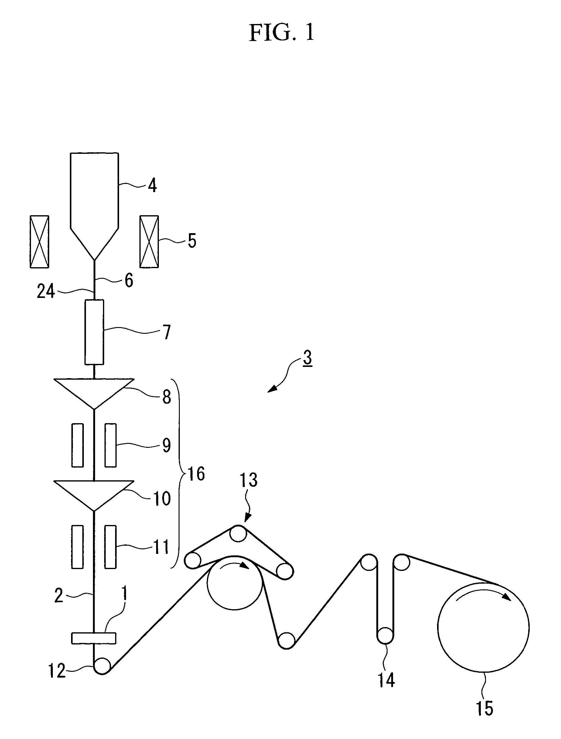
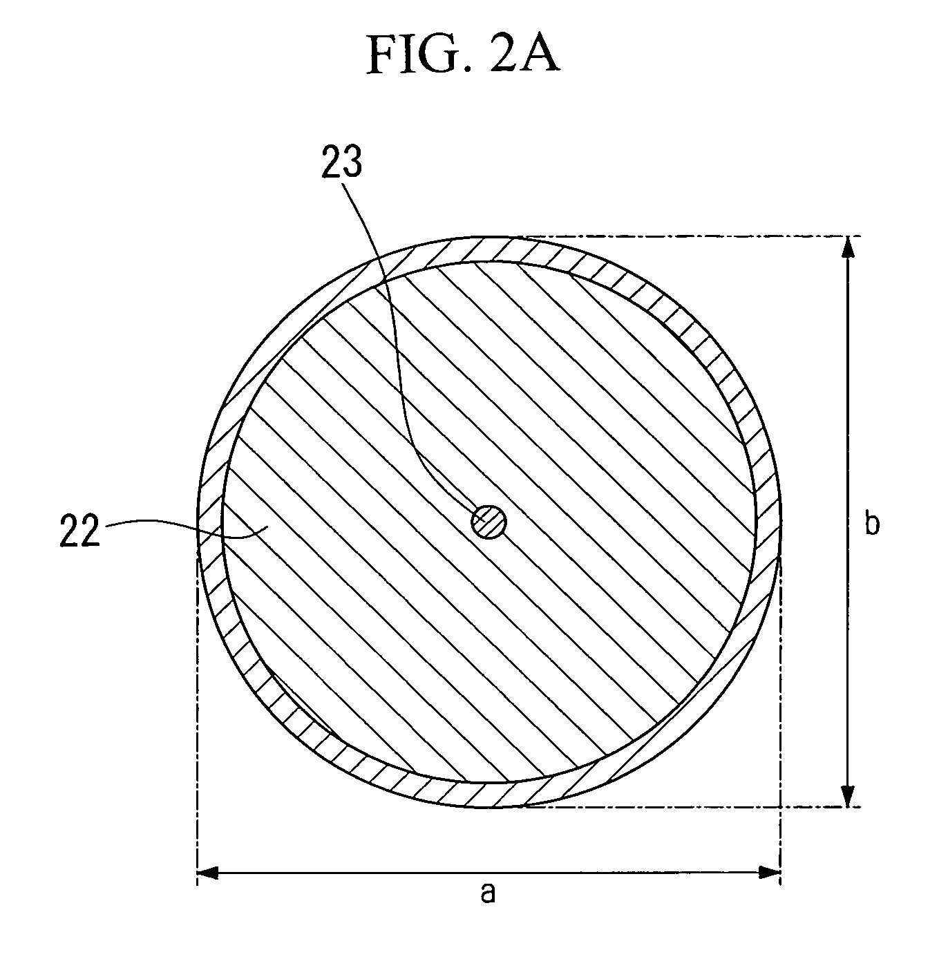
[0062] Using the optical fiber twisting apparatus described in FIG. 1 of Japanese Patent No. 3224235 (i.e., Apparatus A), by adjusting the optical fiber twisting apparatus and using twist rollers in which the values of the accuracy of the outer circumference (a−b) / 2 of the twist roller were 5, 10, and 15 μm, the accuracy of the outer circumference of the twist roller when it formed a part of the twist roller apparatus was set such that (e−f) / 2 was 5, 10, and 15 μm. When the actual drawing was performed and the line distortion was confirmed, no line distortion occurred in the optical fiber during the manufacturing of the optical fiber, which resulted in a consistent coating being provided. Moreover, excellent results were obtained in the warm water delamination test of the manufactured optical fiber. Example 1 in Table 1 indicates the test results.

example 2

[0064] Using the optical fiber twisting apparatus described in FIG. 4 of Japanese Patent No. 3224235 (i.e., Apparatus B), when experiments were performed under the same conditions as in Example 1 (i.e., (e−f) / 2 was 5, 10, and 15 μm), excellent results were obtained for line distortion and warm water immersion delamination. Example 2 in Table 1 indicates the test results.

example 3

[0066] Using the optical fiber twisting apparatus described in FIG. 6 of Japanese Patent No. 3224235 (i.e., Apparatus C), when experiments were performed under the same conditions as in Example 1 (i.e., (e−f) / 2 was 5, 10, and 15 μm), excellent results were obtained for line distortion and warm water immersion delamination. Example 3 in Table 1 indicates the test results.


PUM

PropertyMeasurementUnit
Diameteraaaaaaaaaa
Lengthaaaaaaaaaa
Diameteraaaaaaaaaa

Abstract

An optical fiber twisting apparatus that prevents line distortion in an optical fiber undergoing a drawing process and provides a consistent coating on a bare optical fiber. This optical fiber twisting apparatus includes a twist roller apparatus that having a twist roller that, by imparting a twist to an optical fiber, imparts a twist to a molten portion of an optical fiber preform positioned on an upstream side of the optical fiber, and a support portion that supports the twist roller. The accuracy of the outer circumference of the twist roller when the twist roller is forming a part of the twist roller apparatus is 15 μm or less.

Description

CROSS REFERENCE TO RELATED APPLICATIONS [0001] This application claims priority from PCT Application No. PCT / JP2004 / 018879 filed Dec. 17, 2004, and from Japanese Patent Application No. 2003-432264 filed Dec. 26, 2003, which applications are incorporated herein by reference.BACKGROUND OF THE INVENTION [0002] 1. Field of the Invention [0003] The present invention relates optical fibers and fabrication of optical fibers, and more particularly, the present invention relates to an optical fiber twisting apparatus that imparts a twist to the optical fiber during the fabrication process. The present invention also relates to a method of manufacturing an optical fiber using the optical fiber twisting apparatus, and to an optical fiber manufactured using this method of manufacturing. [0004] 2. Description of the Related Art [0005] Conventionally, an optical fiber twisting apparatus is known whereby in order to reduce polarization mode dispersion (PMD) in an optical fiber there is provided a ...

Claims


Application Information

Patent Timeline
IPC IPC(8): G02B6/00C03B37/027C03B37/03
CPCC03B37/02745C03B37/032C03B2205/06C03B2203/36C03B2203/19
Inventor OKADA, KENJIHARADA, KOICHI
Owner THE FUJIKURA CABLE WORKS LTD
Why Eureka
Try Eureka