Electromagnetically actuated adjusting apparatus for lens
a technology of adjusting apparatus and actuation mechanism, which is applied in the direction of magnetic bodies, printers, cameras focusing arrangements, etc., can solve the problems of consuming more power, prone to bulkyness, and high cost, and achieve high-efficiency focusing or zooming of lenses
- Summary
- Abstract
- Description
- Claims
- Application Information
AI Technical Summary
Benefits of technology
Problems solved by technology
Method used
Image
Examples
first embodiment
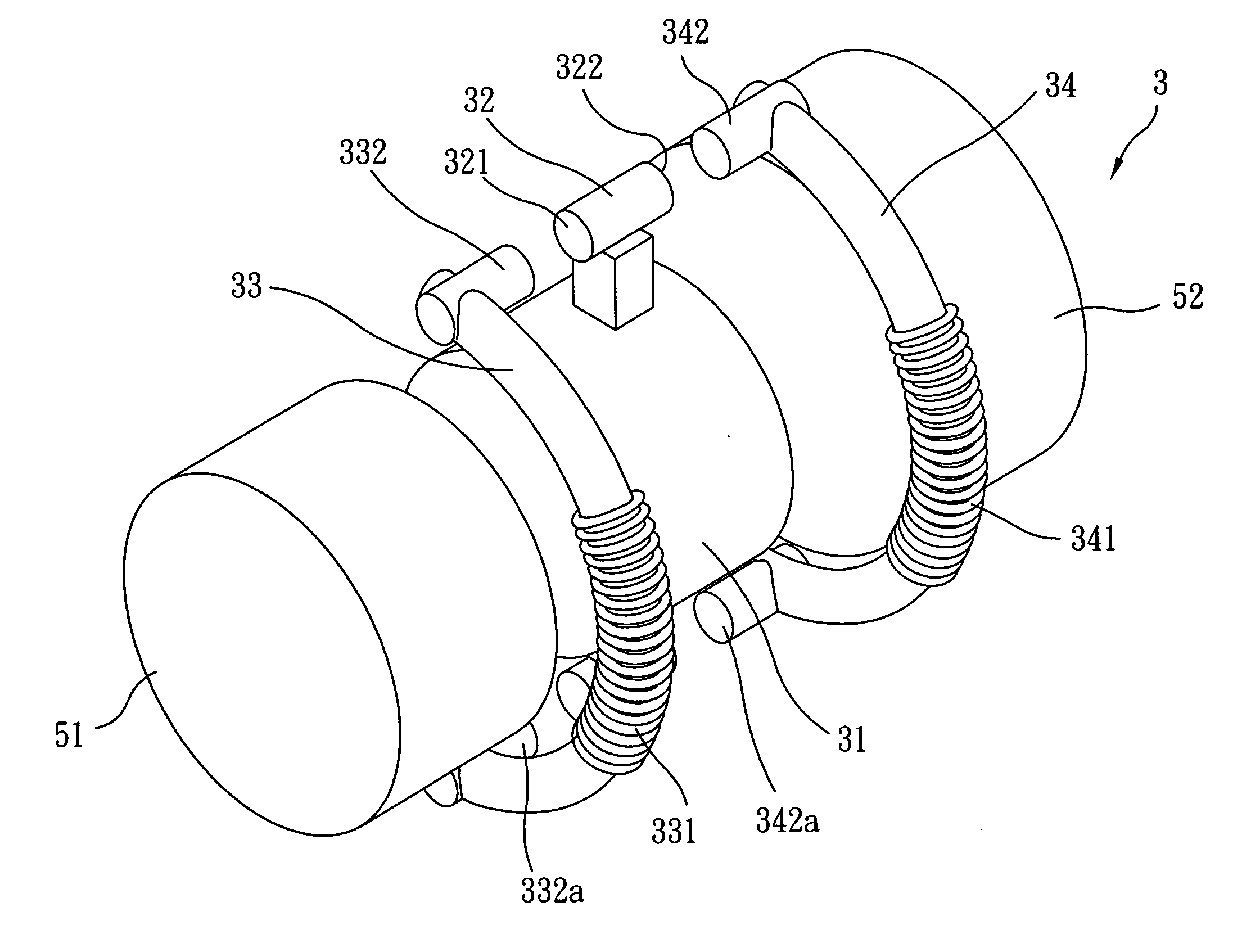
[0029] Referring to FIG. 3A to FIG. 3C which are respectively a perspective view of the electromagnetically actuated adjusting apparatus for lens according to the present invention and side views showing the action of the apparatus. The electromagnetically actuated adjusting apparatus for lens 3 comprises a lens body 31 capable of furnishing a lens inside, at least a permanent magnet 32, a first magnetic conductor 33 and a second magnetic conductor 34. In this preferred embodiment, the electromagnetically actuated adjusting apparatus for lens 3 is used in a camera (e.g. digital camera or mobile phone with digital camera module). Thus the body 31 may be a movable lens set inside the camera lens. Another non-movable anterior lens set 51 may be provided on the left side (front side closer to the object to be shot) of body 31, while an image capturing module 52, e.g. a charge coupled device (CCD) or CMOS image sensor, is disposed on the right side (rear side) of body 31. The aperture of...
third embodiment
[0037]FIG. 5 is a side view of the electromagnetically actuated adjusting apparatus 3b for lens according to the present invention. To achieve the function of more than three-position focusing and zooming, the electromagnetically actuated adjusting apparatus 3b for lens is designed with two aligning members 35b and 35c. The permanent magnet 32 is provided exactly between the two aligning members 35b, 35c and body 31, while the other permanent magnet is also provided between two aligning members 35d, 35e and body 31. In addition, the two aligning members 35b, 35c are disposed between first extension member 332 and second extension member 342. Similarly the other two aligning members 35d, 35e are disposed between another first extension member 332a and another second extension member 342a. In this embodiment, the aligning members 35b, 35c need not be a convexity structure as shown in FIG. 4A, but a rectangular cube structure. Through such design, the body 31 may be positioned at a pla...
fourth embodiment
[0038]FIG. 6 is a side view of the electromagnetically actuated adjusting apparatus 4 for lens according to the present invention. The adjusting apparatus 4 in this embodiment comprises a body 41, at least one permanent magnet set 42, and at least one magnetic conducting member 43. The permanent magnet set 42 is adjoined to body 41 and has a first permanent magnet 421 and a corresponding second permanent magnet 422. Both the first permanent magnet has 421 and the second permanent magnet 422 have a second pole 425, 424 respectively (S pole) which are arranged adjacent to each other, so that both ends of said permanent magnet set 42 have the same first pole 423, 426 (N pole) respectively. The magnetic conducting member 43 is made of magnetically permeable material having a plurality of coils 431 wound around the central portion. The magnetic conducting member 43 has respectively a first extension member 432 and a second extension member 433 at each end respectively. The first extensio...
PUM
 Abstract
Description
Claims
Application Information
 - R&D
- Intellectual Property
- Life Sciences
- Materials
- Tech Scout
- Unparalleled Data Quality
- Higher Quality Content
- 60% Fewer Hallucinations
Browse by: Latest US Patents, China's latest patents, Technical Efficacy Thesaurus, Application Domain, Technology Topic, Popular Technical Reports.
© 2025 PatSnap. All rights reserved.Legal|Privacy policy|Modern Slavery Act Transparency Statement|Sitemap|About US| Contact US: help@patsnap.com


