Sleeve, drill and puncture instrument

a technology of puncture instruments and sleeves, applied in the field of sleeves, drills and puncture instruments, etc., can solve the problems of difficulty in relocating the drilled hole in order to introduce a biopsy needle, and the cost of manufacturing of drills or needles with eccentric drill tips is, for example, more expensive than a conventional drill

Inactive Publication Date: 2006-11-02
APRIOMED
View PDF4 Cites 13 Cited by
  • Summary
  • Abstract
  • Description
  • Claims
  • Application Information

AI Technical Summary

Benefits of technology

[0008] When a drilling operation is completed, typically when the distal end of the needle has penetrated through the cortical bone, the needle is withdrawn, while the sleeve is left in the drill hole. A sampling device, such as a biopsy needle, can then be advanced th

Problems solved by technology

A disadvantage is that the cannula easily can move out of position, making it difficult to relocate the drilled hole in order to, for example, introduce a biopsy needle.
Although the technology described in the above patent represents a progress in comparison with the traditional procedure, it is still accompanied by some disadvantages.
A drill or needle having an eccentric drill tip is, for example, more expensive to manufacture than a conventional drill with a concentric drill tip.
Further, for sharp needles or drills having an acute point angle, the eccentricity of the drill or needle does not work in an optimal way; and for certain punctures

Method used


Image

  • Sleeve, drill and puncture instrument
  • Sleeve, drill and puncture instrument
  • Sleeve, drill and puncture instrument

Examples


Embodiment Construction

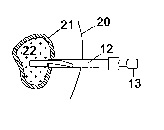
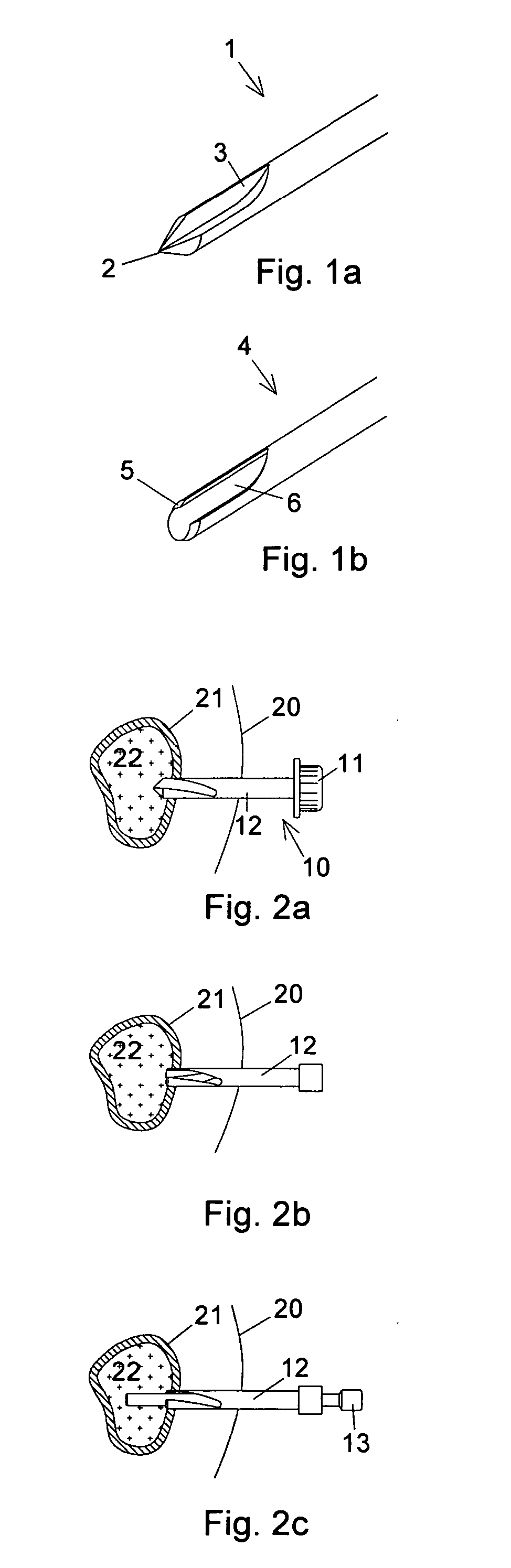
[0012] The basic elements of a puncture instrument according to the present inventions are illustrated in FIGS. 1a and 1b, wherein FIG. 1a shows a distal portion of a needle (or drill) 1, which is provided with a drill tip 2 and a groove 3 (sometimes called a flute), and wherein FIG. 1b shows a distal portion of a sleeve 4, which is provided with a chamfered distal end 5 and a cut (or opening or recess) 6. The inner diameter of the sleeve 4 is closely adapted to the outer diameter of the needle 1. Basically, the needle 1 can be regarded as a conventional drill 1, whereas it is the special features of the sleeve 4—when co-operating with the needle 1—that accomplish a puncture instrument according to this embodiment of the invention. The drill tip 2 of the needle 1 has an angle, which preferably is the same, or almost the same, as the chamfering of the distal end 5 of the sleeve 4. Moreover, the dimensions of the recess 6 in the sleeve 4 are adapted to the dimensions of the groove 3 i...


PUM


Abstract

A surgical puncture instrument (30) includes a drill (31) and a cutter sleeve (36). The sleeve is shaped to continue the shape of the drill so that the sleeve participates in the drilling operation. This permits the sleeve to enter hard tissue and allows the sleeve to be used for access to inner tissue to, for example, obtain a biopsy with a biopsy needle (13).

Description

[0001] Priority is hereby claimed to U.S. Provisional Application 60 / 675,468, filed Apr. 28, 2005, whose entire contents are incorporated herein by reference.FIELD OF THE INVENTION [0002] The present invention relates to a device for the sampling of tissue from a human or animal being, and in particular to a puncture instrument comprising a needle and a sleeve, which together work as a drill. BACKGROUND OF THE INVENTION [0003] One way to gain access to a lesion through a cortical bone is to introduce a conventional spiral drill equipped with a cannula, drill through the cortical bone, and then remove the drill. The cannula remains in place in the soft tissue, but cannot be inserted through the drilled hole in the cortical bone, because the outer diameter of the cannula is larger than the diameter of the drilled hole. A disadvantage is that the cannula easily can move out of position, making it difficult to relocate the drilled hole in order to, for example, introduce a biopsy needle...

Claims


Application Information

Patent Timeline
IPC IPC(8): A61B17/60
CPCA61B17/1617A61B2010/0258A61B17/3472A61B17/1637
Inventor AKERFELDT, DANNICKLASSON, EVA
Owner APRIOMED
Why Eureka
Try Eureka