Method of generating wiring routes with matching delay in the presence of process variation

a technology of process variation and wiring route, applied in the field of balancing delay in, can solve the problems of large delay increase, poor correlation of wire characteristics of wire segments on different wiring levels, source of delay variation in paths on integrated circuits, etc., and achieve the effect of reducing the difference between delays

Active Publication Date: 2006-11-02
GLOBALFOUNDRIES US INC
View PDF4 Cites 14 Cited by
  • Summary
  • Abstract
  • Description
  • Claims
  • Application Information

AI Technical Summary

Benefits of technology

[0016] Thus, one idea of the invention is to create routes for two or more source (beginning) to sink (end) wiring paths such that the paths traverse wire segments of similar lengths on the same wiring levels and i

Problems solved by technology

A significant source of delay variation in paths on an integrated circuit is variation (due predominantly to variations in the manufacturing process) of characteristics, such as height, width, and spacing, of the metal wires used to interconnect the circuit elements of the integrated circuit.
However wire characteristics of wire segments on different wiring levels tend to be very poorly correlated, because they are created during different sets of manufacturing steps.
But an increase in resistance in a wire segment near a net source will cause a larger delay increase than a similar resistance increase in a wire segment near the net sink, because more of the net capacitance must be charged or discharged through that wire segment resistance when a signal transition occurs.
Thus nets with matching delays under nominal conditions can result in significantly different delays under process variation (±9% for 10% parameter variations, in this example).
The fundamental issue is that the even if the delay functions for two nets match at a pa

Method used


Image

  • Method of generating wiring routes with matching delay in the presence of process variation
  • Method of generating wiring routes with matching delay in the presence of process variation
  • Method of generating wiring routes with matching delay in the presence of process variation

Examples


Embodiment Construction

[0026] The present invention and the various features and advantageous details thereof are explained more fully with reference to the nonlimiting embodiments that are illustrated in the accompanying drawings and detailed in the following description. It should be noted that the features illustrated in the drawings are not necessarily drawn to scale. Descriptions of well-known components and processing techniques are omitted so as to not unnecessarily obscure the present invention. The examples used herein are intended merely to facilitate an understanding of ways in which the invention may be practiced and to further enable those of skill in the art to practice the invention. Accordingly, the examples should not be construed as limiting the scope of the invention.

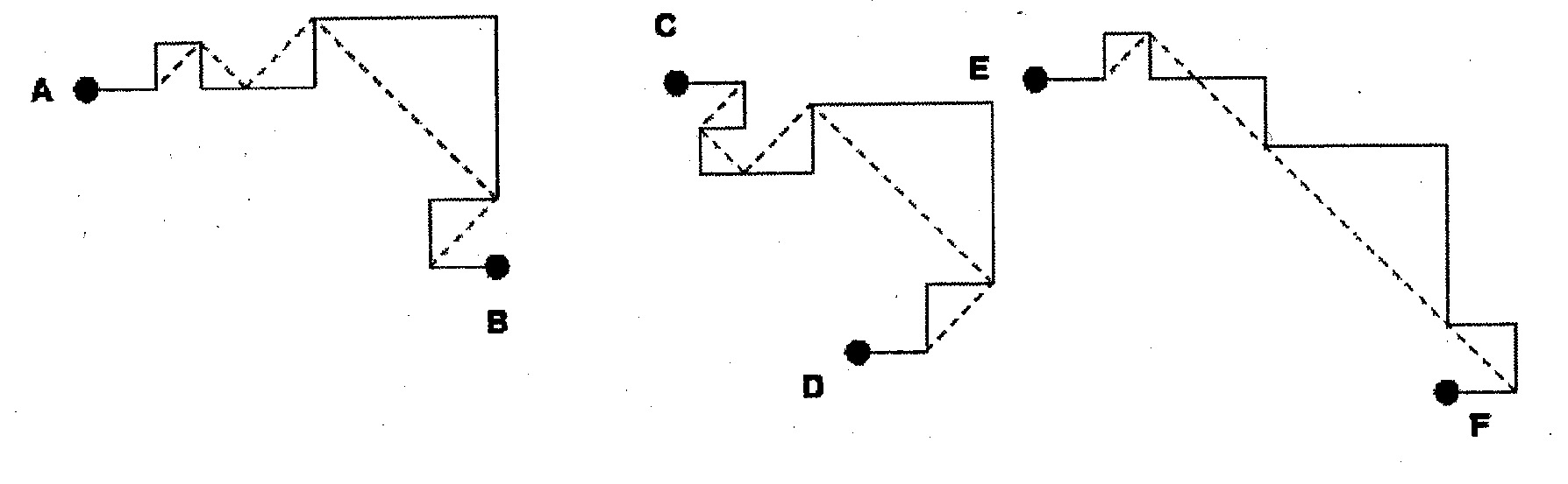
[0027] In the descriptions below it should be understood that collections of horizontal, or X axis distances and wire segments and vertical, or Y axis distances and wire segments may be extended to include distances and wi...


PUM


Abstract

A method and service of balancing delay in a circuit design begins with nodes that are to be connected together by a wiring design, or by being supplied with an initial wiring design that is to be altered. The wiring design will have many wiring paths, such as a first wiring path, a second wiring path, etc. Two or more of the wiring paths are designed to have matching timing, such that the time needed for a signal to travel along the first wiring path is about the same time needed for a signal to travel along the second wiring path, the third path, etc. The method/service designs one or all of the wiring paths to make the paths traverse wire segments of about the same length and orientation, within each wiring level that the first wiring path and the second wiring path traverse. Also, this process makes the first wiring path and the second wiring path traverse the wire segments in the same order, within each wiring level that the first wiring path and the second wiring path traverse.

Description

FIELD OF THE INVENTION [0001] The present invention provides a method of balancing delay in a circuit design that modifies one or all of the wiring paths to make the paths traverse wire segments of about the same length and orientation, within each wiring level that the paths traverse, and to traverse such segments in the same order. DESCRIPTION OF THE RELATED ART [0002] A significant source of delay variation in paths on an integrated circuit is variation (due predominantly to variations in the manufacturing process) of characteristics, such as height, width, and spacing, of the metal wires used to interconnect the circuit elements of the integrated circuit. These interconnecting wires are typically composed of segments on multiple wiring layers (a net is a collection of connected net segments which forms a connection between two or more circuit elements). To maximize the usability of the available space on these wiring layers and to reduce the tendency for one wire segment to bloc...

Claims


Application Information

Patent Timeline
IPC IPC(8): G06F17/50
CPCG06F17/5077G06F30/394
Inventor HABITZ, PETER A.HATHAWAY, DAVID J.HAYES, JERRY D.POLSON, ANTHONY D.
Owner GLOBALFOUNDRIES US INC
Why Eureka
Try Eureka