Adjustable bicycle racks

a bicycle rack and adjustable technology, applied in the field of bicycle racks, can solve the problem that bicycles cannot be well fastened

Inactive Publication Date: 2006-11-09
WANG CHIU KUEI
View PDF9 Cites 40 Cited by
  • Summary
  • Abstract
  • Description
  • Claims
  • Application Information

AI Technical Summary

Benefits of technology

[0006] The primary object of the present invention is to provide a bicycle rack that includes a pull member for pulling the adjustable member relative to the base so as to adjust the space for clamping bicycle frames of different sizes.

Problems solved by technology

However, the shape and size of the bicycle frames varies for modem bicycles, the cross sections of top tubes of bicycle frames can be circular, oval or even polygonal shapes so that the bicycle cannot be well fastened and might shake on the bicycle rack.

Method used


Image

  • Adjustable bicycle racks
  • Adjustable bicycle racks
  • Adjustable bicycle racks

Examples


Embodiment Construction

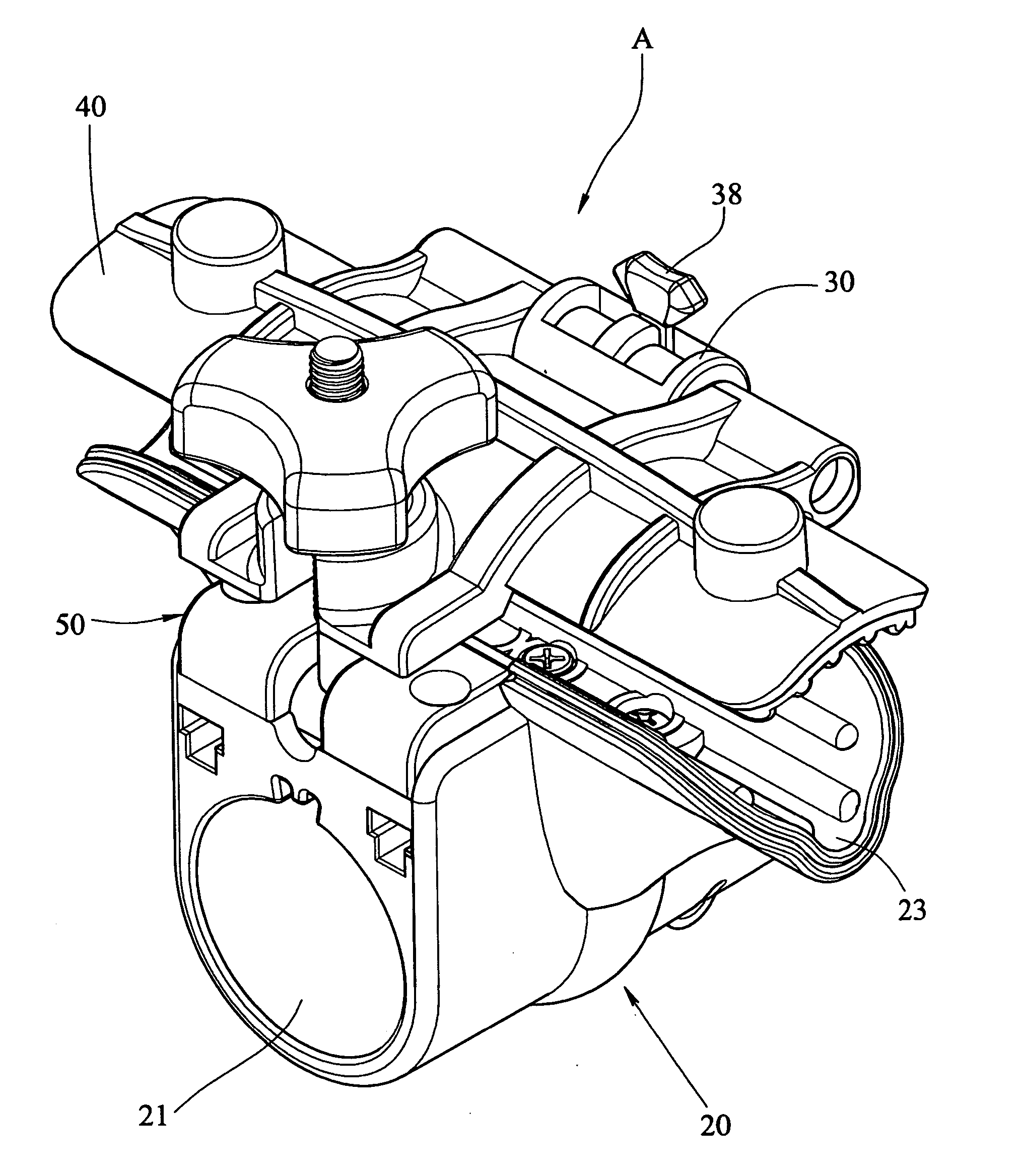
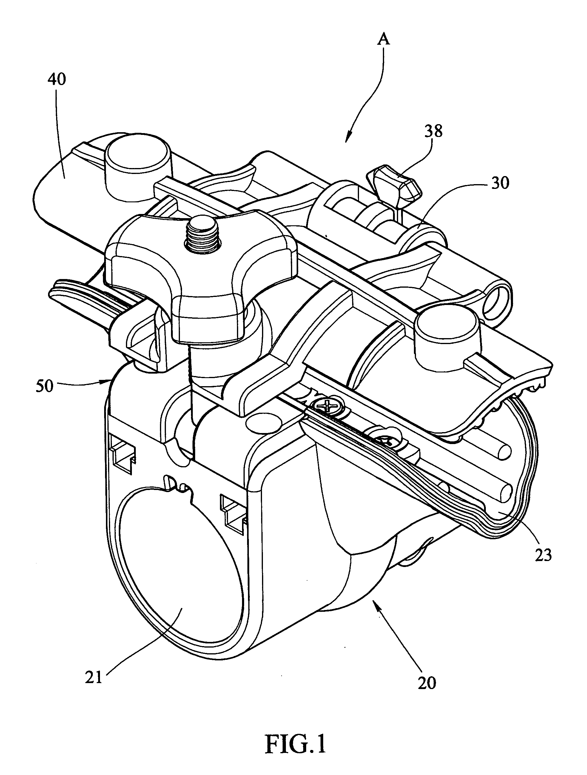
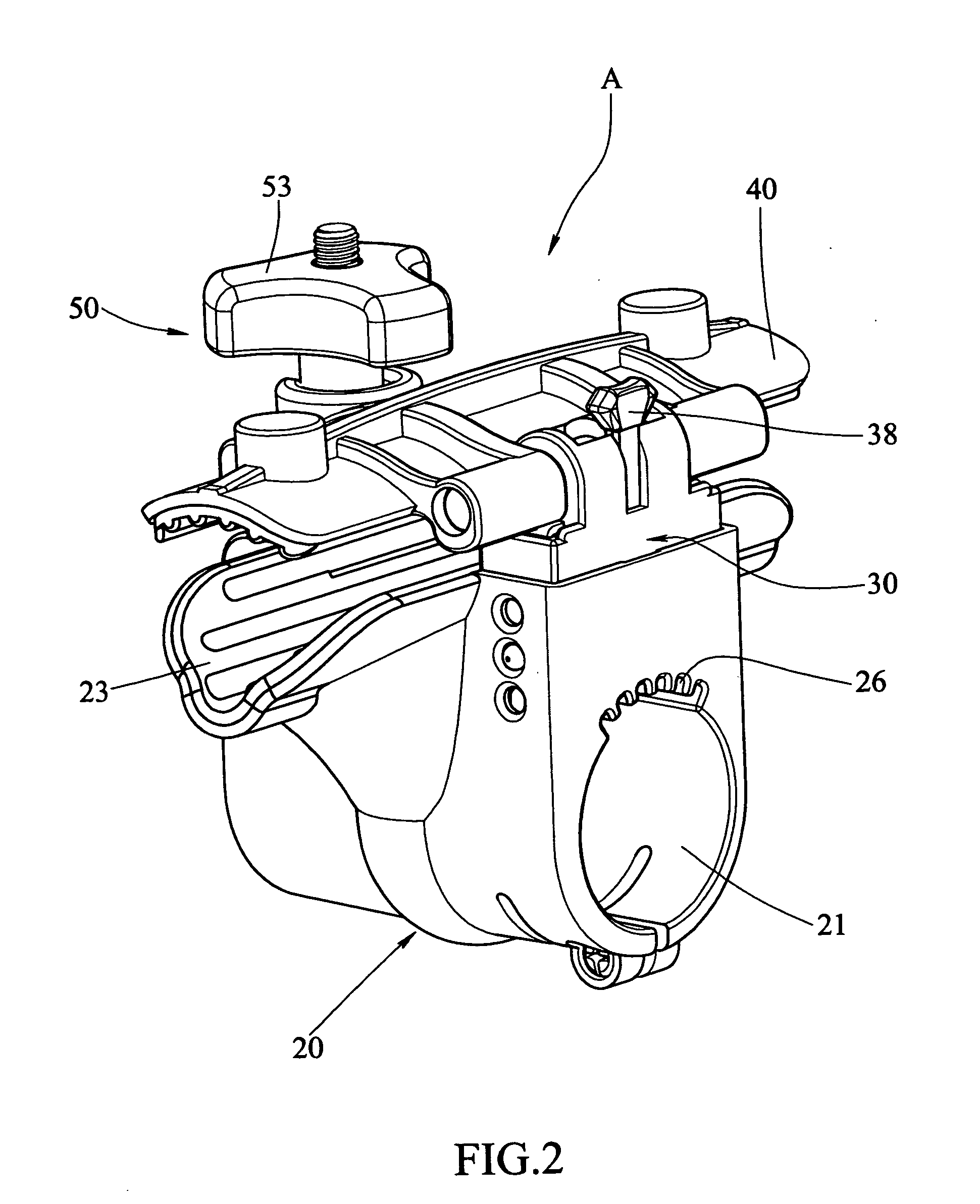
[0019] Referring to FIGS. 1 to 4, the bicycle rack “A” of the present invention comprises a base 20 having a passage 21 defined in a lower part thereof through which a transverse bar 11 of a rod 10 connected to a vehicle extends. A plurality of axial grooves 26 are defined in an inside of the passage 21 and a positioning piece 13 is fixed to an outside of the transverse bar 11 by inserting two ends of the positioning piece 13 into holes 12 defined in the transverse bar 11. A V-shaped clamping recess 23 is defined in a top of the base 20 and a chamber 25 is defined in a rear of the base 20. rubber plates 231 are connected to a surface of the clamping recess 23. A central slot 24 is defined in an inside of the clamping recess 23 and in communication with the passage 21 of the base 20. A set of pressing plates is inserted in the central slot 24 and includes a first pressing plate 27 and a second pressing plate 28. The first pressing plate 27 includes two lugs 273 on two ends thereof an...


PUM


Abstract

A bicycle rack includes a base connected to a transverse bar of a rod on the vehicles. An adjustable member has a lower part with an open bottom and the adjustable member is inserted in a chamber defined in a rear of the base. A spring member is received in the lower part and connects the lower part to two sidewalls of the chamber. A pull member is connected to the adjustable member and hooked to the spring member. A cover member is pivotably connected to the adjustable member so as to clamp bicycle frames between the cover member and the base. A fastening device is pivotably connected to a front of the base and the cover member is connected to the fastening device. The cover member can be pivoted to pull the pull member to pull the spring member so as to adjust the adjustable member relative to the base. By this way, the distance between the cover member and the base can be adjusted.

Description

FIELD OF THE INVENTION [0001] The present invention relates to a bicycle rack connected to vehicles and the bicycle rack can be adjusted according to bicycle frames of different sizes. BACKGROUND OF THE INVENTION [0002] A conventional bicycle rack 60 connected to vehicles is shown in FIG. 8 and generally includes a transverse bar 61 and a positioning member 62 is connected to the transverse bar 61. The positioning member 62 includes a plurality of notches 63 for receiving bicycle frames therein. A top member 64 is connected to the positioning member 62 and fastening devices 66 are used to lock the top member 64 to the positioning member 62 so that the bicycle frames can be fixed between the top member 64 and the positioning member 62. [0003] However, the shape and size of the bicycle frames varies for modem bicycles, the cross sections of top tubes of bicycle frames can be circular, oval or even polygonal shapes so that the bicycle cannot be well fastened and might shake on the bicy...

Claims


Application Information

Patent Timeline
Patent Type & Authority Applications(United States)
IPC IPC(8): A47F7/00
CPCB62H3/02
Inventor WANG, CHIU-KUEI
Owner WANG CHIU KUEI
Why Eureka
Try Eureka