Reusable container for retail display of electric cable components

a technology for electric cables and containers, applied in the field of packaging, can solve the problems of easy damage to the electrical cable easy to be damaged, etc., and achieve the effects of convenient storage, simple and aesthetically attractive, and low manufacturing cos

Inactive Publication Date: 2006-11-09
SCOTT RINGO
View PDF20 Cites 58 Cited by
  • Summary
  • Abstract
  • Description
  • Claims
  • Application Information

AI Technical Summary

Benefits of technology

[0008] An advantage of the present invention is that it is simple and aesthetically attractive. Another advantage of the present invention is that it is inexpensive to manufacture. Another advantage of the present invention is that it provides a simplified and easy storage. Another advantage of the present invention is that it provides a storage system that is aesthetically appealing, and light-weight. Other advantages of the present invention will become apparent from the following descriptions, taken in connection with the accompanying drawings, wherein, by way of illustration and example, an embodiment of the present invention is disclosed.
[0009] The preferred embodiment of the present invention comprises a reusable container for storing and merchandising electronic cabling. The container generally comprises a box portion, a lid, and a latch portion. The box portion comprises a base having four sides extending upwards from the perimeter of the base, forming a substantially rectangular box edge opposite the base. An outwardly inverted flange is formed along the box edge. The lid is removable and comprises a lid topside and an opposite lid underside. A groove is formed adjacent to the perimeter of the lid underside. The groove is complementarily engagable with the top of the flange when the lid is place on the box. A recess is formed on the lid topside. A generally semi-cylindrical latch has one or more anchors on one side and corresponding latch hooks on its opposite side. The latch hooks are pivotally attached to corresponding latch slots formed in the flange. The anchors are complementarily engagable with the recess of the lid topside for securing the lid to the box portion.
[0010] In another preferred embodiment of the present invention, the container further comprises a hanger removably attached to the flange on one end, and having a hole or aperture for attachment to a retail display device. In a more preferred embodiment, the hanger has one or more hanger hooks pivotally attached to corresponding hanger slots formed in the flange.
[0011] In another preferred embodiment of the present invention, the box portion and lid are made of a transparent material.
[0012] In another preferred embodiment of the present invention, the container comprises a sheath configured to slidably engage the box and the lid. Additionally, in another preferred embodiment of the present invention, the sheath is formed of cardboard or configured to contain printed material on at least one surface.
[0013] In another preferred embodiment of the present invention, the recess of the lid topside has a relief portion in which the recess is enlarged to accommodate finger actuation of the latch.

Problems solved by technology

However, simply hanging cables for displays poses a number of problems.
Specifically, it is very easy for a customer to accidentally be caught by the coil causing injury or damage.
Moreover, repackaging the cable can be cumbersome.
In many cases, adhesive tags are employed to maintain the coiled cables, but the adhesive tags are not easily repaired.
Additionally, once a customer purchases the cable, storage can become a cumbersome task because there is no immediate storage device or method.
This process provides a water-tight packaging that is very often difficult to remove, even when scissors are used.
Opening the package risk damage to the contents and injury to the buyer.
The prior art designs for cable packaging are difficult to remove and not reusable.

Method used


Image

  • Reusable container for retail display of electric cable components
  • Reusable container for retail display of electric cable components
  • Reusable container for retail display of electric cable components

Examples


Embodiment Construction

[0030] The following description is presented to enable any person skilled in the art to make and use the invention, and is provided in the context of a particular application and its requirements. Various modifications to the disclosed embodiments will be readily apparent to those skilled in the art, and the general principles defined herein may be applied to other embodiments and applications without departing from the spirit and scope of the present invention. Thus, the present invention is not intended to be limited to the embodiments shown, but is to be accorded the widest scope consistent with the principles and features disclosed herein.

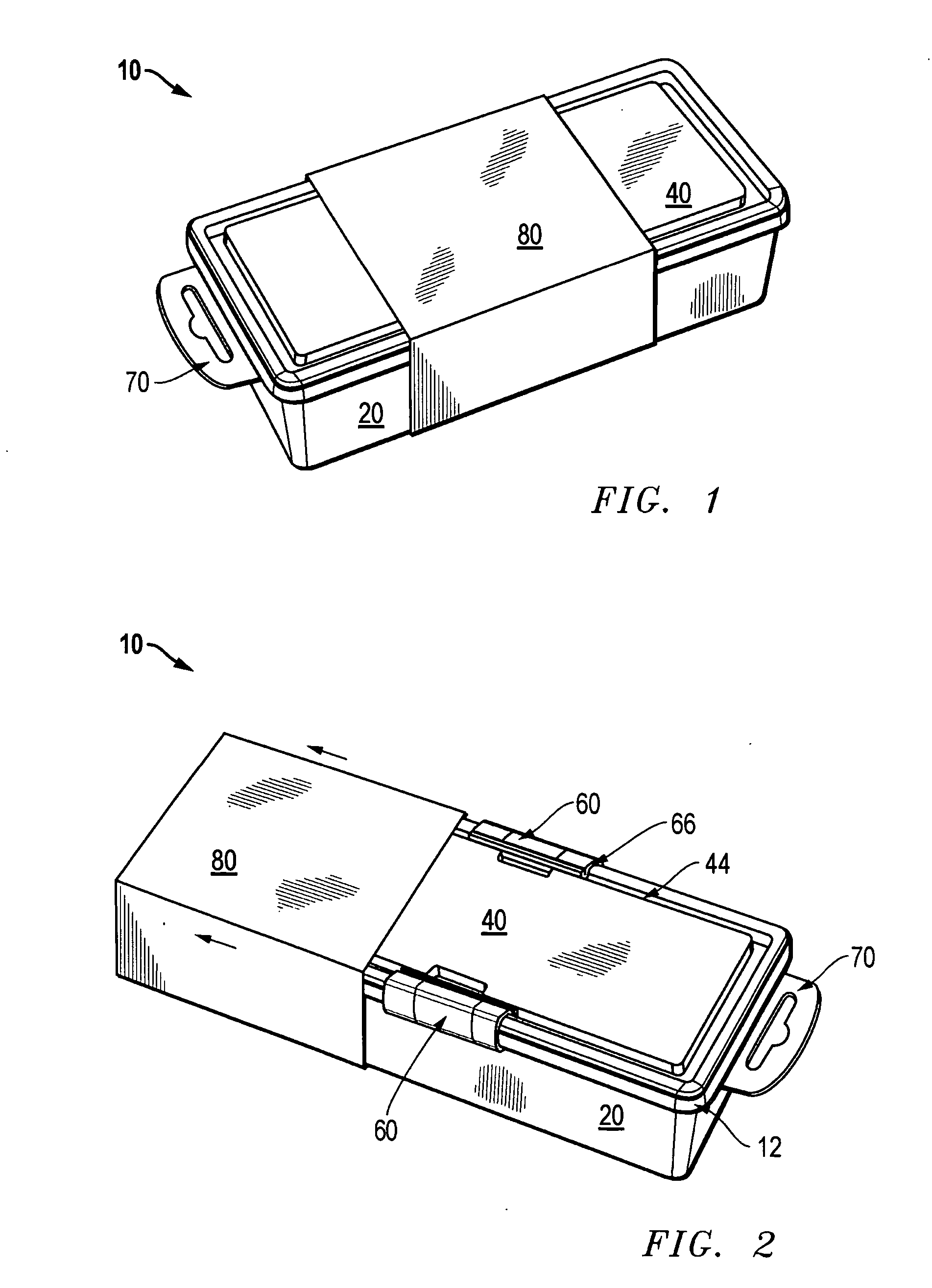
[0031]FIG. 1 is an isometric view of a reusable retail container 10 illustrated in accordance with a preferred embodiment of the present invention. Reusable retail container 10 comprises a box 20, a removable lid 40, and a slidably removable sheath 80. When fully assembled, lid 40 rests on the top of box 20 and sheath 80 slidably covers box 2...


PUM

PropertyMeasurementUnit
perimeteraaaaaaaaaa
transparentaaaaaaaaaa
flexibleaaaaaaaaaa

Abstract

A packaging assembly is provided for storing and merchandising electric components, such as electrical cables. Until now, cables and other electrical components have typically in disposable container, which were generally not reusable, and often require knives or tools to open, risking damage and injury. However, to combat problems associated with conventional devices and techniques, an easy-to-use reusable packaging assembly is employed. The packaging assembly utilizes a box and a lid that are coupled together with latch assemblies. Then, a sheath can slidably engage the box and lid to allow for, ease of marketing. The combination then allows for easy storage and mechanizing for cables that has not become available until now.

Description

CLAIM OF PRIORITY [0001] This application claims priority from U.S. Design patent application Ser. No. ______ entitled “REUSABLE RETAIL DISPLAY AND STORAGE UNIT FOR ELECTRONICS COMPONENTS” (Attorney Docket No. DSC 03392 DPUS) and from U.S. Design patent application Ser. No. ______ entitled “SHEATHED REUSABLE RETAIL DISPLAY AND STORAGE UNIT FOR ELECTRONICS COMPONENTS” (Attorney Docket No. DSC 03393 DPUS), both of which were filed on Apr. 15, 2005.TECHNICAL FIELD OF INVENTION [0002] The present invention relates to packaging, and in particular, to convenient packaging for electric cables and similar components. BACKGROUND OF THE INVENTION [0003] It has long been desirable to have a convenient package that can be employed for use with electrical cables and similar components. There have been numerous attempts to conveniently package electrical cords that allow for both ease of display and ease of storage. [0004] Traditionally, cords have been simply coiled. Typically, the cables are co...

Claims


Application Information

Patent Timeline
Patent Type & Authority Applications(United States)
IPC IPC(8): B65D41/16B65D45/16B65D25/10
CPCB65D45/20B65D25/22Y02W30/80
Inventor RINGO, SCOTT ANDREW
Owner SCOTT RINGO
Why Eureka
Try Eureka