Package for receiving electronic parts, and electronic device and mounting structure thereof

a technology for electronic parts and mounting structures, applied in semiconductor devices, semiconductor/solid-state device details, electrical apparatuses, etc., can solve the problems of inability to securely bond electronic parts to heat radiating plates, and insufficient heat radiating properties, so as to achieve effective blockage of stress on heat radiating plates, effective prevention of cracks, and smooth operation

Inactive Publication Date: 2006-11-09
KYOCERA CORP
View PDF5 Cites 33 Cited by
  • Summary
  • Abstract
  • Description
  • Claims
  • Application Information

AI Technical Summary

Benefits of technology

[0028] According to the present invention, a heat radiating plate constituting a package for receiving electronic part includes a metallic base body in a flame shape, a metallic body filling inside of the metallic base body, and a metal layer deposited on the metallic base body and the metallic body. A mounting area is formed on the metal layer so as to be located above the metallic body, both the metallic body and the metal layer have higher thermal conductivity than the metallic base body, and both the frame body and the metallic base body have a smaller coefficient of thermal expansion than the metal layer. Accordingly, more heat generated from the electronic part can be transferred in the direction vertical to the mounting surface of the electronic part owing to the metallic body and be effectively diffused into the air or to an external radiating member through the heat radiating plate.
[0035] According to the present invention, a carbon sheet or grease is interposed between the main surface of the metallic body opposite to the metal layer and the heat radiating member. Thus, it is possible to effectively prevent a gap from being generated between the metallic body and the heat radiating member, to transfer heat generated from the electronic part to the heat radiating member far more efficiently, and to improve heat radiation reliability to the heat radiating member.

Problems solved by technology

However, thermal conductivity of the conventional heat radiating plate consisting of the copper-tungsten material or the copper-molybdenum material is about 200 W / m·K, which is lower than the desired thermal conductivity.
Therefore, the heat radiating property is becoming insufficient.
Yet, in this case, difference of coefficients of thermal expansion between the electronic part and the heat radiating plate is increased and thus it is impossible to securely bond the electronic part onto the heat radiating plate.

Method used


Image

  • Package for receiving electronic parts, and electronic device and mounting structure thereof
  • Package for receiving electronic parts, and electronic device and mounting structure thereof
  • Package for receiving electronic parts, and electronic device and mounting structure thereof

Examples


Embodiment Construction

[0042] Suitable embodiments of the present invention will now be described in detail with reference to the accompanying drawings.

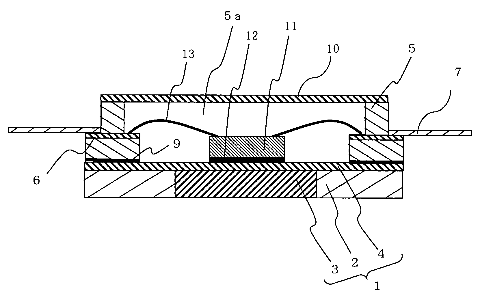
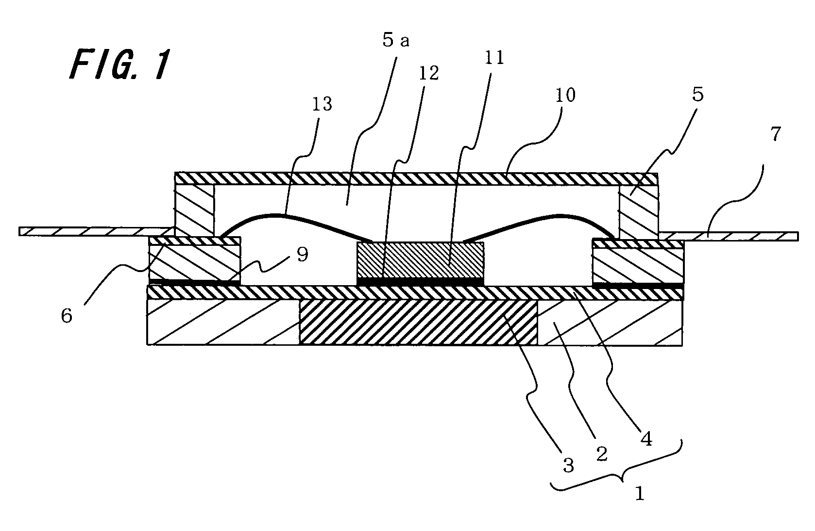
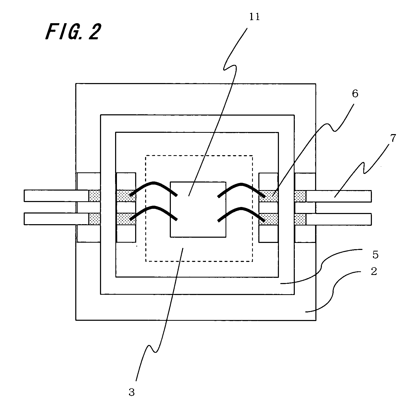
[0043]FIG. 1 is a cross sectional view illustrating a package for receiving electronic part and an electronic device according to a first embodiment of the present invention. FIG. 2 is a plane perspective view of the package for receiving the electronic part of FIG. 1. The package for receiving the electronic part includes a heat radiating plate 1, a metallic base body 2, a metallic body 3, a metal layer 4, a frame body 5, a wiring conductor 6, a lead terminal 7, and a cover body 10. The heat radiating plate 1, the frame body 5, and the wiring conductor 6 configure a package for receiving electronic part 11. After the electronic part 11 is mounted on a mounting area 12 of the heat radiating plate 1, the cover body 10 is adhered over a concave part 5a, which is formed by the heat radiating plate 1 and the frame body 5, so as to cover the mounting area 12, ...


PUM


Abstract

A package for receiving electronic part has a heat radiating plate having a mounting area where the electronic part is mounted at a center portion of one main surface, a frame body adhered to the one main surface to surround the mounting area, and a wiring conductor derived from the inside to the outside of the frame body. The heat radiating plate has a metallic base body, a metallic body filling inside of the metallic base body, and a metal layer deposited on the metallic base body and the metallic body. The mounting area is formed on the metal layer so as to be located above the metallic body, both of the metallic body and the metal layer have higher thermal conductivity than the metallic body, and both of the frame body and the metallic base body have a smaller coefficient of thermal expansion than the metal layer.

Description

BACKGROUND OF THE INVENTION [0001] 1. The Field of the Invention [0002] The present invention relates to a package for receiving an electronic part with a heat radiating structure having good heat radiating property, an electronic device using the same, and a mounting structure of the electronic device. [0003] 2. Description of Prior Art [0004] In the related art, a package for receiving an electronic part such as semiconductor elements, generally includes a frame body formed of an electrical insulating material such as aluminum oxide sintered material, mullite sintered material, glass ceramic sintered material, and the like, a heat radiating plate formed of copper-tungsten material or copper-molybdenum material for effectively radiating heat generated from operation of the mounted electronic part to outside or into the air, and a cover body. The frame body is disposed on one main surface of the heat radiating plate so as to surround the mounting area of the electronic part. In addi...

Claims


Application Information

Patent Timeline
Patent Type & Authority Applications(United States)
IPC IPC(8): H01L23/34H01L23/10
CPCH01L23/047H01L2924/19107H01L2224/32188H01L2224/48227H01L2924/01012H01L2924/0102H01L2924/01025H01L2924/01046H01L2924/01078H01L2924/01079H01L2924/09701H01L2924/15153H01L2924/1517H01L2924/16152H01L2924/16195H01L2924/3025H01L24/48H01L2924/01019H01L2924/12041H01L2224/73265H01L23/4334H01L2924/00014H01L2224/45099H01L2224/45015H01L2924/207
Inventor MIYAUCHI, MASAHIKO
Owner KYOCERA CORP
Why Eureka
Try Eureka