Current sensing for power MOSFETs

a power mosfet and current sensing technology, applied in the direction of current measurement only, measurement devices, instruments, etc., can solve the problems of inaccurate current sensing, affecting the accuracy of load current determined in this manner, and requiring a relatively negative power supply

Inactive Publication Date: 2006-11-09
POWER INTEGRATIONS INC
View PDF9 Cites 50 Cited by
  • Summary
  • Abstract
  • Description
  • Claims
  • Application Information

AI Technical Summary

Benefits of technology

[0022] Another aspect of the invention provides a circuit comprising: a current-sensing MOSFET having gate, drain, source, and mirror terminals; a current sense resistor coupled between the mirror terminal and a connection to the source terminal; a control device for selectively changing current through the current sensing resistor to produce first and second voltages selectively at the mirror terminal; an ADC (analog-to-digital converter) arranged to produce digital values representing the first and second voltages; and digital logic responsive to the digital values to monitor current of the MOSFET. The control device can comprise a switch for selectively changing a resistance of the cur

Problems solved by technology

However, virtual ground current sensing has the significant disadvantages of requiring a relatively negative power supply and producing a relatively negative output voltage.
As a larger resistance value appreciably increases the total resistance in the current mirror path, it makes the gate-source voltage of the current mirror section different from that of the main section

Method used


Image

  • Current sensing for power MOSFETs
  • Current sensing for power MOSFETs
  • Current sensing for power MOSFETs

Examples


Embodiment Construction

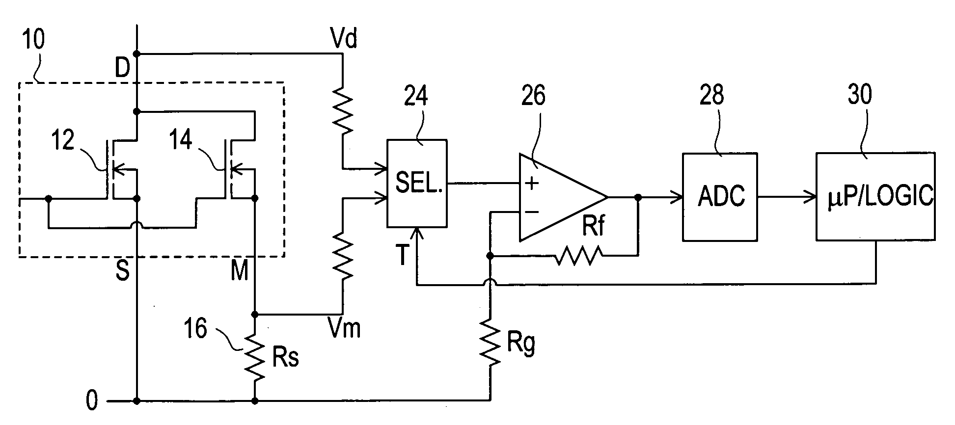
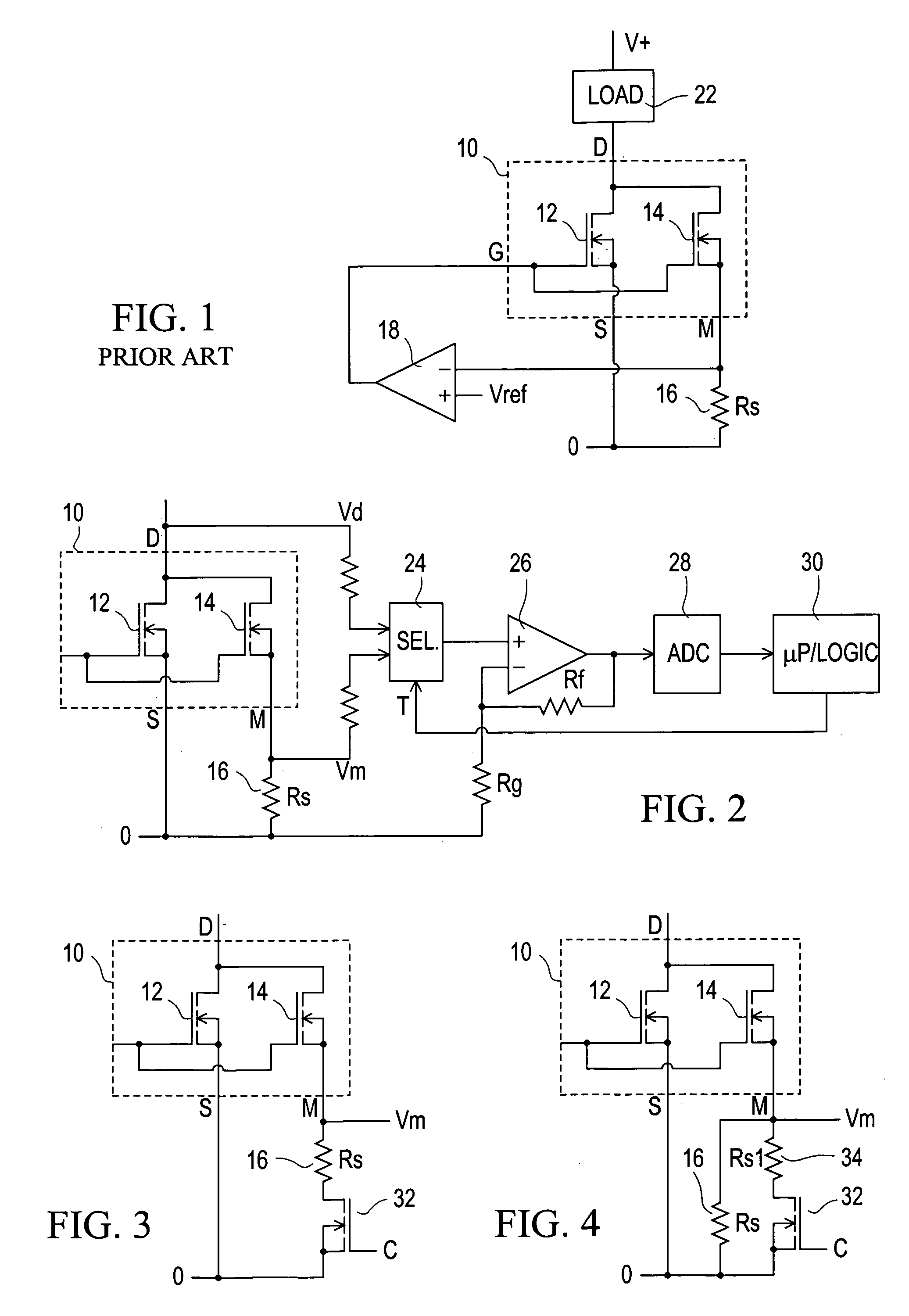
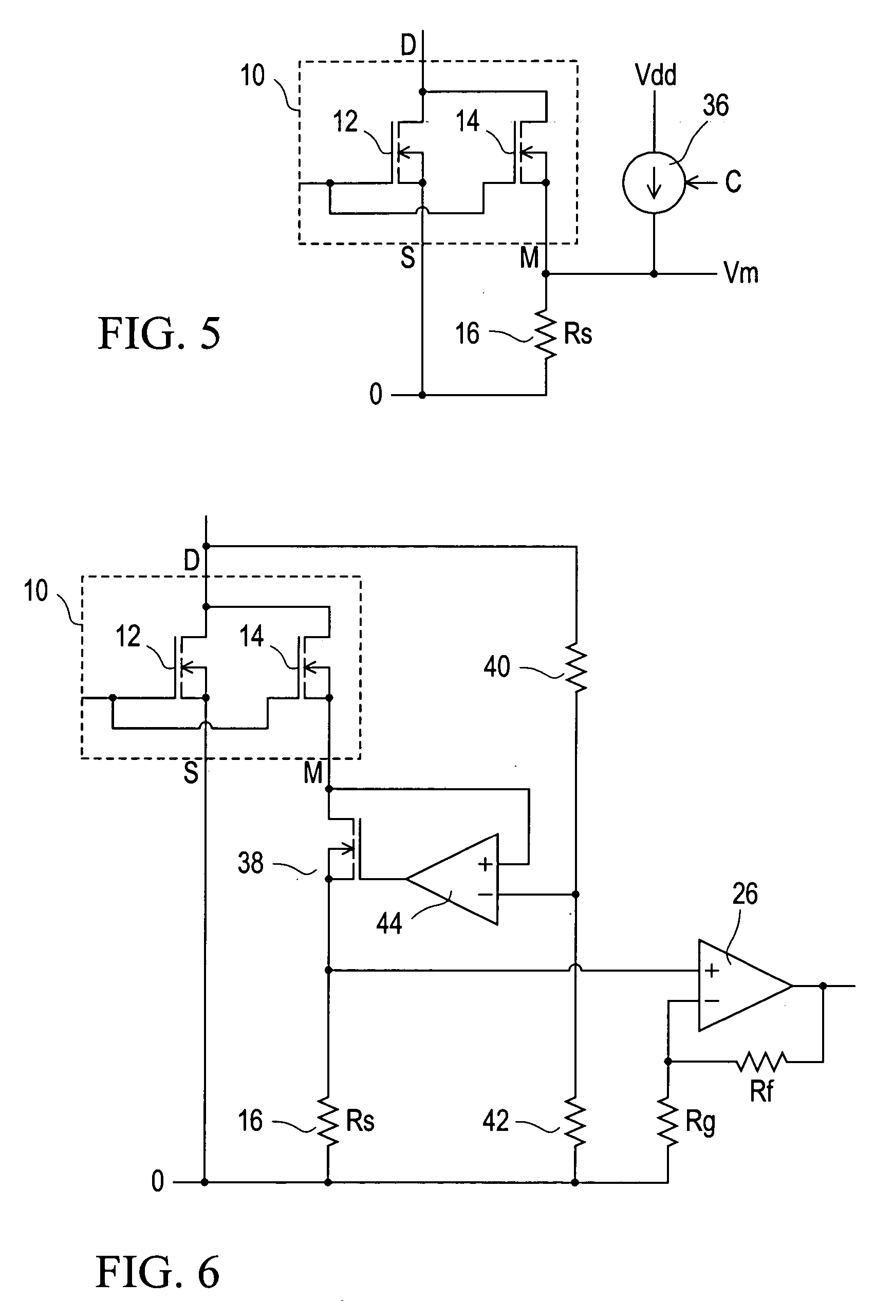
[0031] Referring to the drawings, FIG. 1 illustrates a known circuit including a current sensing power MOSFET 10, indicated within a dashed-line box, which comprises a main MOSFET 12 and a current mirror or current sensing MOSFET 14. The MOSFETs 12 and 14 have their gates connected together and to a common gate terminal G, and their drains connected together and to a common drain terminal D. The source of the main MOSFET 12 is connected to a source terminal S, and the source of the current mirror MOSFET 14 is connected to a mirror terminal M. There is a predetermined ratio k of transistor cells of the MOSFET 12 to transistor cells of the MOSFET 14; for example k may be of the order of 100 to 1000.

[0032] Because all of the transistor cells of an individual power MOSFET 10 are similar, if the gate-source voltage Vgs and the gate-mirror voltage Vgm are equal, then substantially (ignoring effects due for example to bulk resistance of MOSFET conductors) the MOSFETs 12 and 14 pass curren...


PUM


Abstract

A power MOSFET, comprising main and current mirror MOSFETS, has a current sense resistance coupled between its mirror and source terminals and a monitoring circuit responsive to a first voltage dependent upon current through the current sense resistance. The circuit arrangement includes a circuit that determines a second voltage, different from the first voltage, of a terminal of the current mirror MOSFET, and a circuit arranged to determine current of the power MOSFET in dependence upon the first and second voltages. The second voltage can be the voltage at the drain terminal, or the voltage at the mirror terminal with switching of the current sense resistance or a current that it passes. It can alternatively be determined by a control circuit to be a desired fraction of the drain voltage.

Description

[0001] This invention relates to current sensing for power MOSFETs, and is particularly concerned with facilitating accurate current measurement for a current sensing MOSFET without requiring use of a virtual ground circuit. BACKGROUND [0002] A power MOSFET typically comprises a large number of MOSFET transistor cells all connected in parallel with one another, i.e. with their gates connected together, their drains connected together, and their sources connected together. In order to facilitate sensing a load current of a power MOSFET when it is conductive or switched on, without requiring a series resistor to pass all of the load current and hence have a significant and undesired power dissipation, it is known to provide a current sensing MOSFET in which a relatively small number of the transistor cells (referred to as the current mirror section) of the MOSFET have a separate source terminal, referred to as a mirror or sense terminal. A current sensing resistor can be connected bet...

Claims


Application Information

Patent Timeline
IPC IPC(8): G01R31/26
CPCG01R19/0092
Inventor COLBECK, ROGER
Owner POWER INTEGRATIONS INC
Why Eureka
Try Eureka