
Video coding method and apparatus for reducing mismatch between encoder and decoder

a video coding and encoder technology, applied in the field of video coding, can solve the problems of difficult to solve problems, requires high-capacity storage media and broad bandwidth, and cannot meet consumer's various demands, so as to improve overall video compression efficiency, reduce drift error, and efficiently re-estimate high-frequency frames

Inactive Publication Date: 2006-11-09
SAMSUNG ELECTRONICS CO LTD
View PDF4 Cites 18 Cited by
  • Summary
  • Abstract
  • Description
  • Claims
  • Application Information

AI Technical Summary

Benefits of technology

The present invention provides a method and apparatus for improving video compression efficiency by reducing drift error between an encoder and a decoder in an MCTF-based video codec. It also efficiently re-estimates a high-frequency frame and performs an update step at a current layer using the lower layer information in an MCTF-based multi-layered video codec. The technical effects of the invention include improved video compression efficiency, reduced drift error, efficient re-estimated high-frequency frames, and improved video decoding.

Problems solved by technology

The existing text-based communication is insufficient to satisfy consumers' various demands.
Since multimedia data is large, it requires high-capacity storage media and broad bandwidth at the time of transmission.
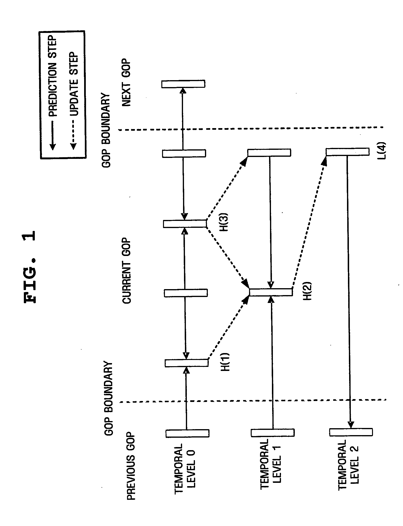
However, in the open-loop structure, the reference frame used in the encoder and the reference frame used in the decoder are not the same, and therefore it is difficult to solve the problem where severe drift error is generated as compared to that of the closed-loop process.
Although drift error can be reduced using the update step, the mismatch between the encoder and the decoder cannot be fundamentally eliminated compared to the closed-loop.
Therefore, a decrease in performance is inevitable.
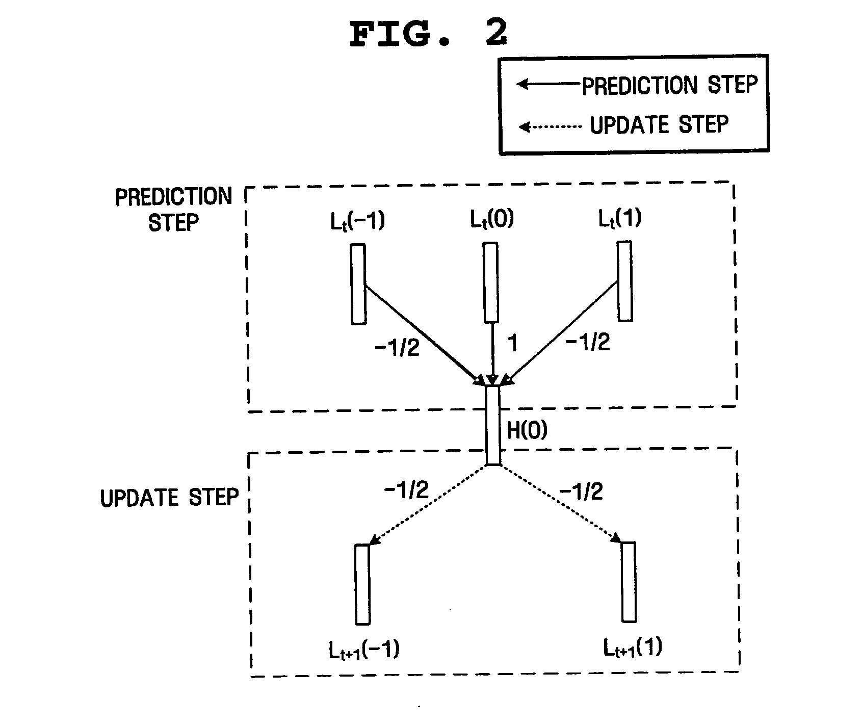
The first is a mismatch in the prediction step.
However, since the right-hand and left-hand reference frames have not yet been quantized, the decoder cannot recognize that the H frame produced in this manner is an optimal signal.
It is difficult in the MCTF structure to consider the previous quantization of the reference frames, as is done in the closed-loop process.
Since the high-frequency frame has not yet been quantized, the mismatch between the decoder and the encoder occurs even in this case.

Method used


Image

  • Video coding method and apparatus for reducing mismatch between encoder and decoder
  • Video coding method and apparatus for reducing mismatch between encoder and decoder
  • Video coding method and apparatus for reducing mismatch between encoder and decoder

Examples


Embodiment Construction

[0047] The present invention will now be described in detail in connection with exemplary embodiments with reference to the accompanying drawings.

[0048] A “closed-loop frame re-estimation method” proposed by the present invention is performed using the following processes.

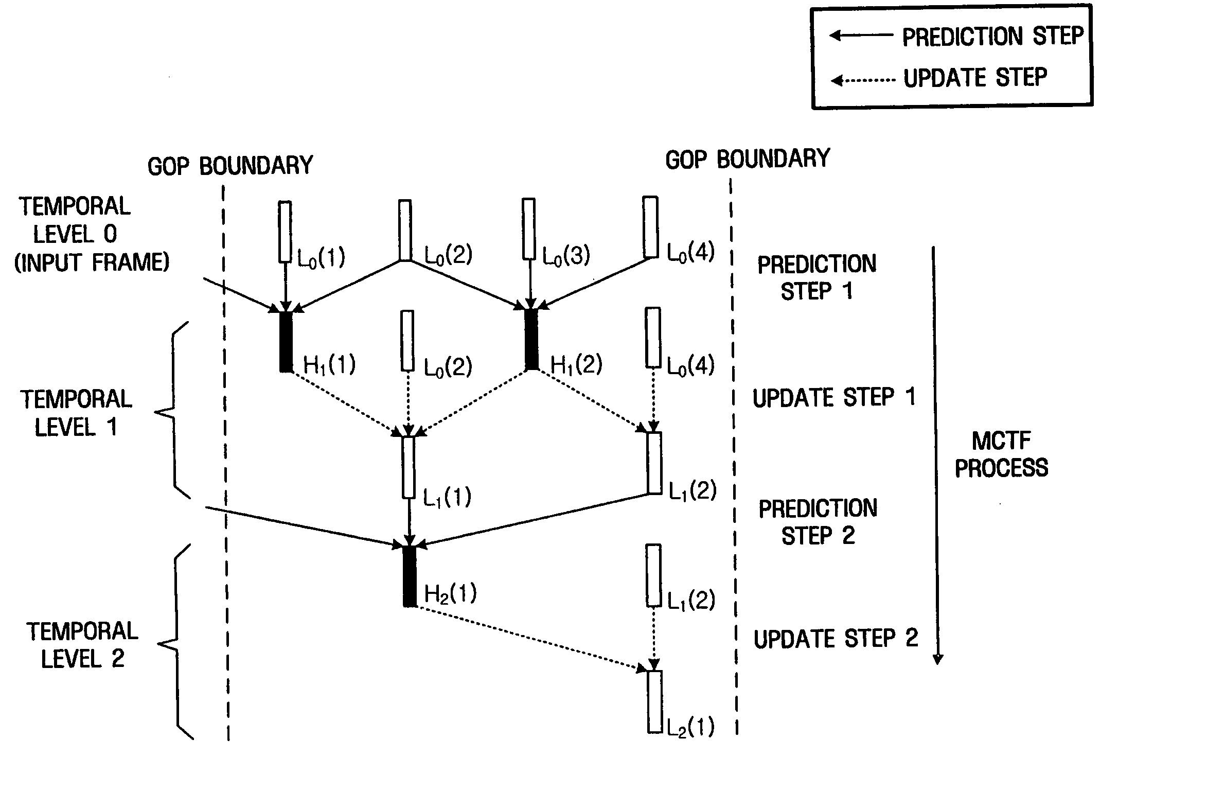
[0049] First, when the size of a GOP is M after the existing MCTF has been performed, M−1 H frames and one L frame are obtained.

[0050] Second, an environment is conformed to that of a decoder by coding / decoding right-hand and left-hand reference frames while performing MCTF in an inverse manner.

[0051] Third, a high-frequency frame is recalculated using the encoded / decoded reference frames.

[0052] Furthermore, a method of implementing a “closed-loop update”, which is proposed by the present invention, includes the following three modes.

[0053] Mode 1 involves reducing a mismatch by omitting an update step for the final L frame

[0054] Mode 2 involves replacing an H frame used in the update step with the informati...


PUM


Abstract

A method of reducing a mismatch between an encoder and a decoder in motion compensated temporal filtering, and a video coding method and apparatus using the same. The video coding method includes dividing input frames into one final low-frequency frame and at least one high-frequency frame by performing motion compensated temporal filtering on the input frames; encoding the final low-frequency frame and decoding the encoded final low-frequency frame; re-estimating the at least one high-frequency frame using the decoded final low-frequency frame; and encoding the re-estimated high-frequency frame.

Description

CROSS-REFERENCE TO RELATED APPLICATIONS [0001] This application claims priority from Korean Patent Application No. 10-2005-0052425 filed on Jun. 17, 2005 in the Korean Intellectual Property Office, and U.S. Provisional Patent Application No. 60 / 670,702 filed on Apr. 13, 2005 in the United States Patent and Trademark Office, the disclosures of which are incorporated herein by reference in their entirety.BACKGROUND OF THE INVENTION [0002] 1. Field of the Invention [0003] Methods and apparatuses consistent with the present invention relate generally to video coding, and more particularly, to reducing a mismatch between an encoder and a decoder in motion compensated temporal filtering. [0004] 2. Description of the Prior Art [0005] As information and communication technology, including the Internet, develops, image-based communication, text-based communication, and voice-based communication are increasing. The existing text-based communication is insufficient to satisfy consumers' variou...

Claims


Application Information

Patent Timeline
Patent Type & Authority Applications(United States)
IPC IPC(8): H04N11/02
CPCH04N19/61H04N19/31H04N19/63H04N19/13H04N19/615H04N19/53
Inventor HAN, WOO-JINLEE, BAE-KEUN
Owner SAMSUNG ELECTRONICS CO LTD
Learn More