Device for holographic reconstruction of three-dimensional scenes

a three-dimensional scene and display device technology, applied in the field of display devices for holographic reconstruction of three-dimensional scenes, can solve the problems of large, voluminous, difficult, difficult, etc., and achieve the effect of reasonable computation load and large cell pitch

Active Publication Date: 2006-11-09
SEEREAL TECHNOLOGIES
View PDF5 Cites 151 Cited by
  • Summary
  • Abstract
  • Description
  • Claims
  • Application Information

AI Technical Summary

Benefits of technology

[0027] Considering the above-mentioned disadvantages of prior art solutions, the object of this invention is to provide a device for encoding large-area video holograms using a conventional spatial light modulator with a relatively large cell pitch so to achieve high-quality real-time holographic reconstructions with reasonable effort of computation load while avoiding the aforementioned disadvantages.

Problems solved by technology

Difficulties occur when realizing an illumination system to illuminate each partial hologram with the required coherence and under the correct reconstruction angle.
Here, a visibility region, which would typically be rather large, is limited to the locally positioned observer windows.
However, the known solution exhibits the disadvantage that a large, voluminous, heavy and thus expensive lens is required for focusing due to the large SLM surface area.
Consequently, the device will have a large depth and weight.
Another disadvantage is represented by the fact that the reconstruction quality is reduced significantly due to aberrations at the margins when using such large lenses.
A further disadvantage of the known embodiments is an insufficient luminous intensity of the SLM.

Method used


Image

  • Device for holographic reconstruction of three-dimensional scenes
  • Device for holographic reconstruction of three-dimensional scenes
  • Device for holographic reconstruction of three-dimensional scenes

Examples


Embodiment Construction

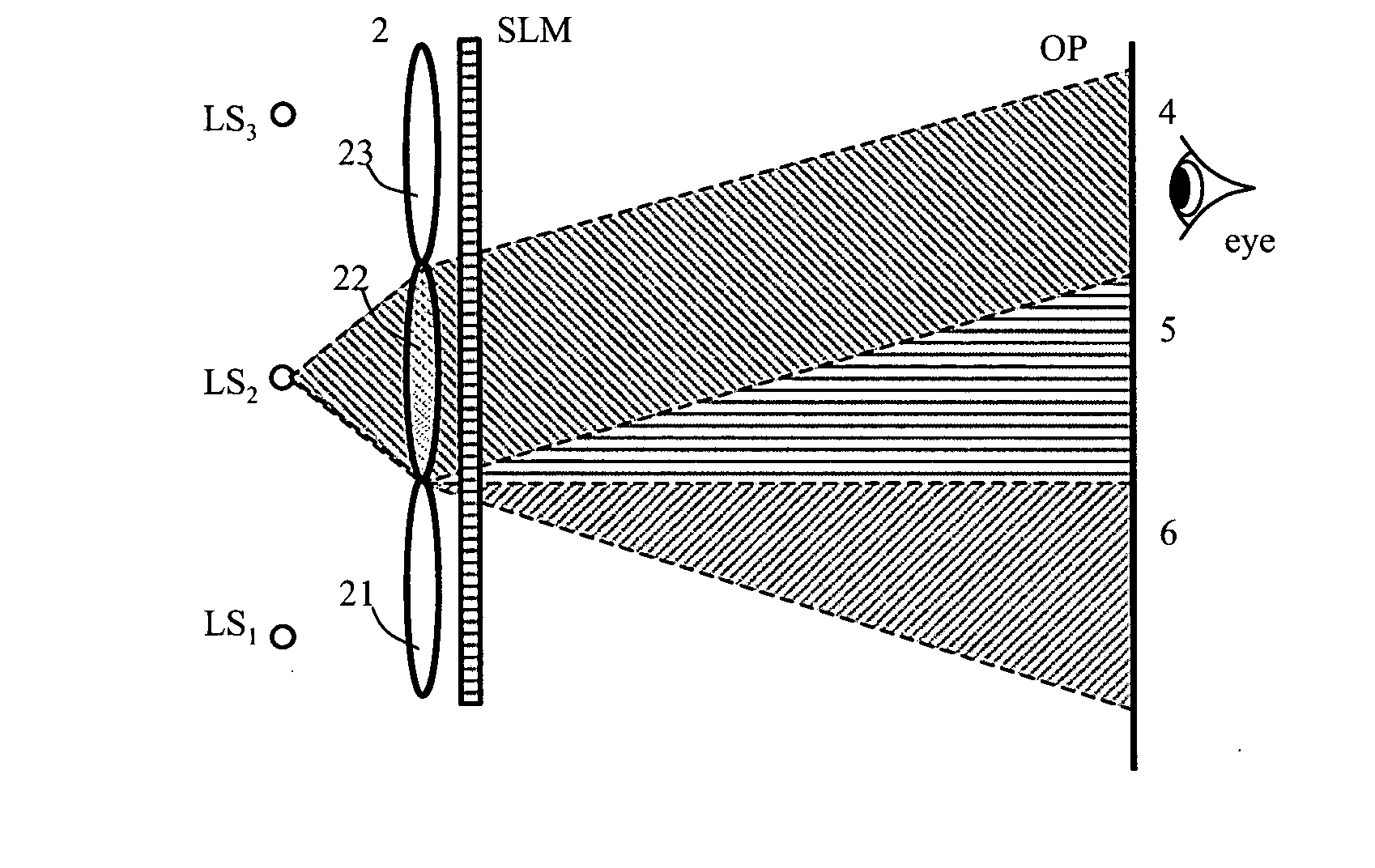
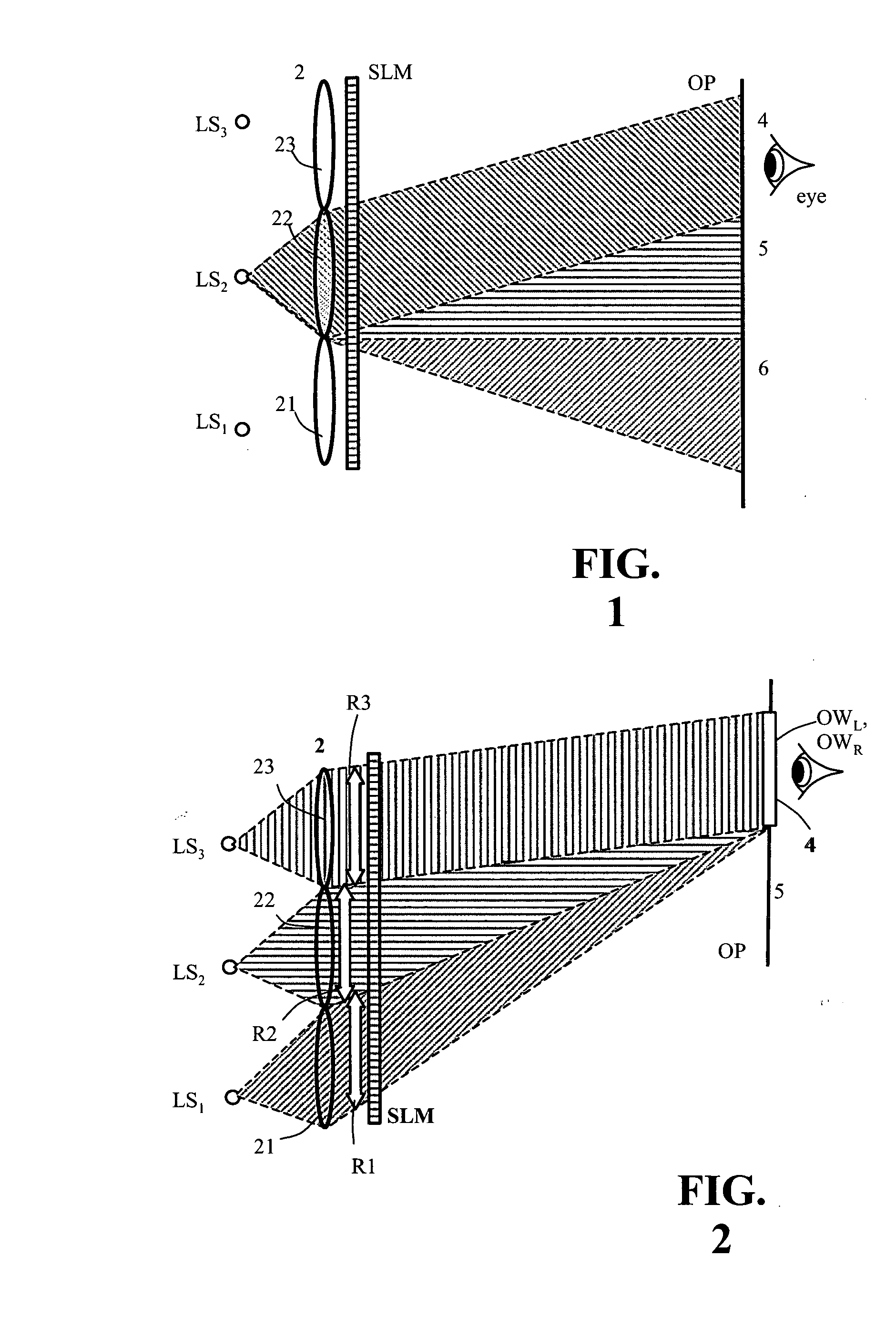
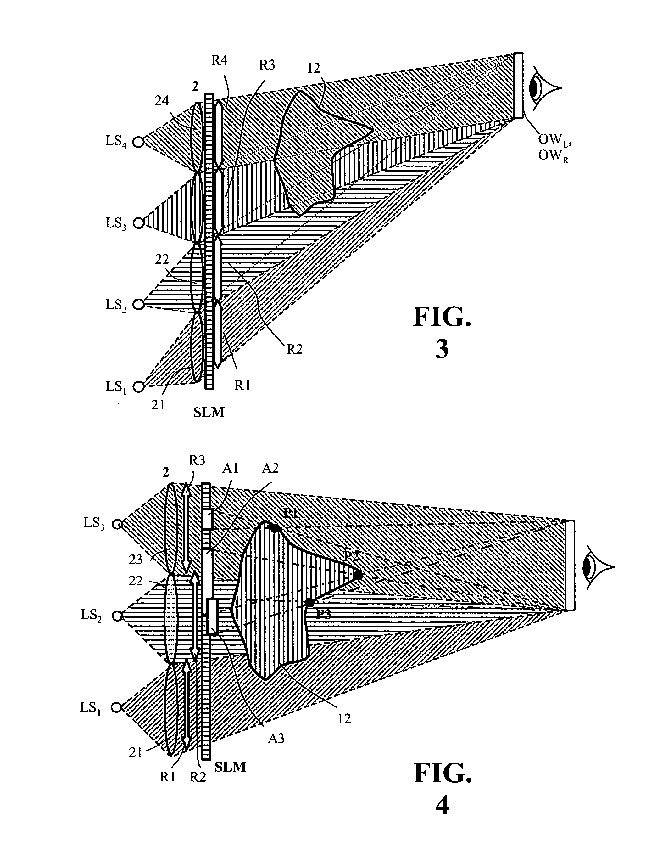
[0058] These drawings schematically show details of the holographic display.

[0059] In the described embodiment, a video hologram is encoded in a transmissive spatial light modulator SLM. However, transflective and reflective light modulators SLM may also be used, preferably those which directly modulate the phase of the light waves, such as Freedericksz cells.

[0060] Further, for better understanding, the described embodiment explains the use of one-parallax encoded holograms for reconstructing a 3D-scene by a combination of a holographic and an auto-stereoscopic display. Such a specific embodiment using spatial-multiplexing of reconstructions is proposed in applicant's patent applications WO2006 / 027228 (US2006 / 050340). This allows a combination of line light sources, lenticular and further optical elements for conventional auto-stereoscopic image separation. The image separation means needed for separation of the two spatially multiplexed parallax holograms are not the object of t...


PUM


Abstract

A device for holographic reconstruction of three-dimensional scenes includes optical focusing means which directs sufficiently coherent light from light means to the eyes of at least one observer via a spatial light modulator that is encoded with holographic information. The device has a plurality of illumination units for illuminating the surface of the spatial light modulator (SLM); each unit comprises a focusing element (21/22/23 or 24), and a light means (LS1/LS2/LS3 or LS4) that emits sufficiently coherent light such that each of these illumination units illuminates one separate illuminated region (R1/R2/R3 or R4) of the surface, whereby the focusing element and the light means are arranged such that the light emitted by the light means (LS1-LS4) coincides close to or at the observer eyes.

Description

BACKGROUND OF THE INVENTION [0001] 1. Field of the Invention [0002] This invention relates to a display device for reconstructing three-dimensional (3D-) scenes using large-area computer-generated video holograms (CGH) encoded in a spatial light modulator which includes electronically controllable cells. Said cells modulate the amplitude and / or phase of light by encoding each cell with hologram values corresponding to a video-hologram. Like auto-stereoscopic displays, reconstructions of video holograms also aim to present moving two- or three-dimensional scenes using a video display. [0003] In this document a CGH describes a hologram that is calculated from a scene. The CGH comprises complex-valued numbers representing the amplitude and phase of light waves that are needed to reconstruct the scene. The CGH may be calculated e.g. by coherent ray tracing, by simulating the interference between light reflected by the scene and a reference wave, or by Fourier or Fresnel transforms. [000...

Claims


Application Information

Patent Timeline
Patent Type & Authority Applications(United States)
IPC IPC(8): G03H1/08
CPCG03H1/2286G03H2210/30G03H2001/2236G03H2001/2242G03H2001/2263G03H2222/20G03H2222/22G03H2222/23G03H2222/24G03H2222/34G03H2223/12G03H2223/19G03H2225/55G03H2225/60G03H2226/05G03H2240/51G03H1/2249G03H1/2294G03H2223/14G03H2222/36G03H2001/2297G03H1/22H04N13/00
Inventor SCHWERDTNER, ARMINHAUSSLER, RALFLEISTER, NORBERT
Owner SEEREAL TECHNOLOGIES
Why Eureka
Try Eureka