Sterile hand held slit lamp cover and method

a technology of slit lamp and cover, which is applied in the field of sterile drapes or covers for slit lamps, can solve the problems that the known sterile surgical cover may not be ideally suited for use during laser eye surgery and ophthalmic examination

Inactive Publication Date: 2006-11-09
AMO MFG USA INC
View PDF17 Cites 5 Cited by
  • Summary
  • Abstract
  • Description
  • Claims
  • Application Information

AI Technical Summary

Benefits of technology

[0008] In an first aspect, the invention provides a sterile barrier for use with a slit lamp. The slit lamp has a proximal handle and a distal light slit transmitting window. The sterile barrier comprises a flexible tubular membrane having a first end, a second end, and an opening therebetween. A resilient band is attached to the first end of the tubular membrane so that an opening of the resilient band is substantially coextensive with the opening adjacent the first end. The resilient band has a relaxed configuration and resiliently expanded configuration. The resilient band in the relaxed configuration is as small or smaller than the cross-section of the slit lamp between the handle and the window so that the resilient band will releasably restrain the sterile barrier from moving proximally off the handle.
[0011] The first end of the tubular membrane may be defined by a fold, with the resilient band being disposed between an inner layer of membrane material and an outer layer of membrane material, the inner and outer layers separated by the fold. A proximal portion of the tubular membrane near the second opening may fittingly receive the handle therein with sufficient tightness to facilitate secure manipulation of the slit lamp while grasping the handle through the proximal portion. A distal portion of the tubular membrane may be sized to allow local movement of membrane material with movement of a variable position sliding input of the slit lamp while the slit lamp adjacent to the sliding input is disposed within the distal portion.

Problems solved by technology

In particular, known sterile surgical covers may not be ideally suited for use during laser eye surgery and ophthalmic examinations.

Method used


Image

  • Sterile hand held slit lamp cover and method
  • Sterile hand held slit lamp cover and method
  • Sterile hand held slit lamp cover and method

Examples


Embodiment Construction

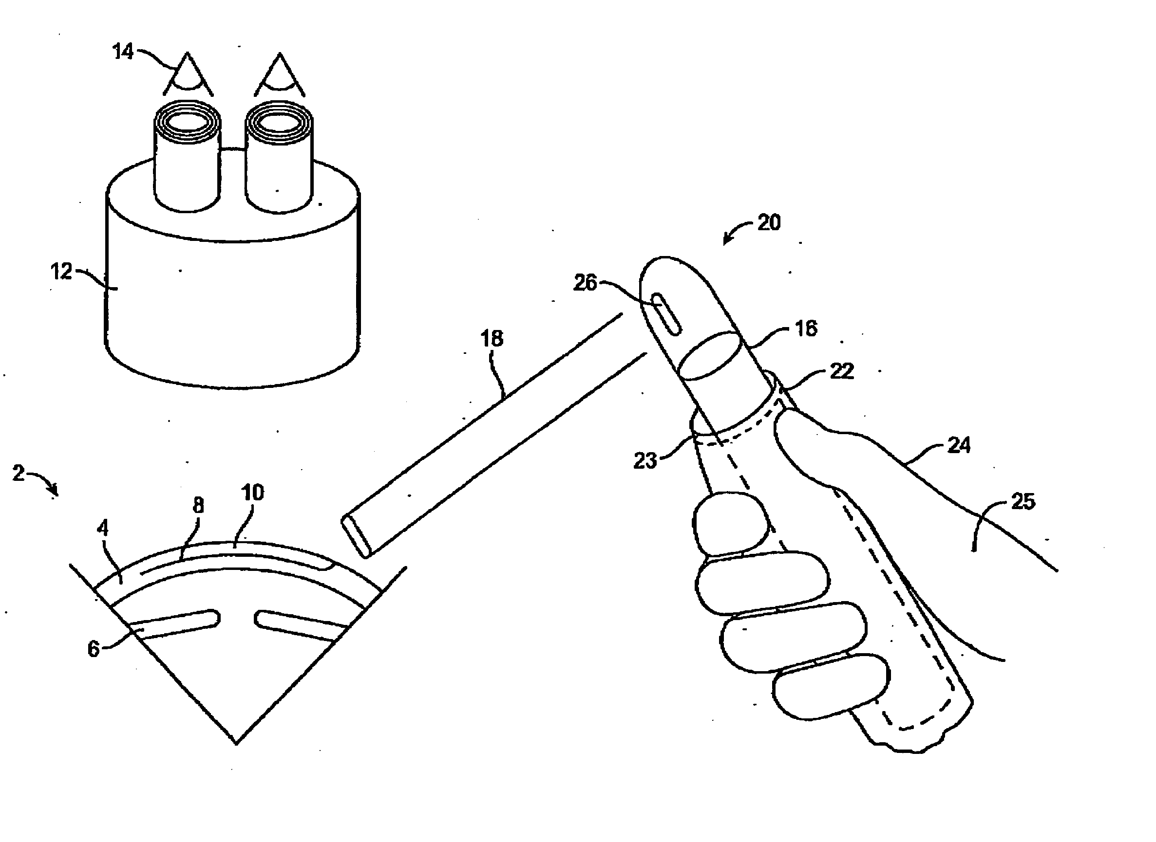
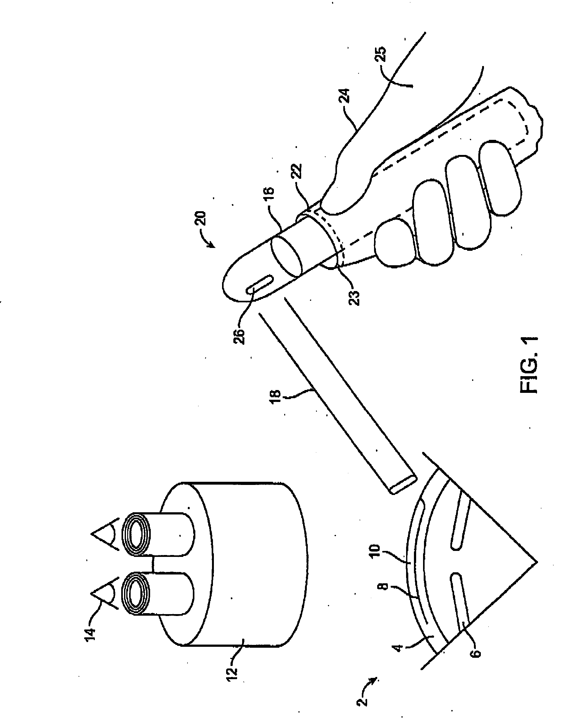
[0022] As illustrated in FIG. 1, a hand held sterile slit lamp system includes a hand held slit lamp 20 held by a hand 25 of an operator 14 and an operating microscope 12 in accordance with an embodiment of the invention. A sterile glove 24 covers the hand 25 of the operator 14. A sterile flexible disposable cover 22 covers a handle 16 of the hand held slit lamp 20. A beam of light 18 passes through a window 26 of the hand held slit illuminator and illuminates an eye 2. Eye 2 includes a cornea 4, and an iris 6. An incision 8 in cornea 4 is covered by a LASIK flap 10 following cutting with a microkeratome. Operating microscope 12 enlarges a size of eye 2 as seen by operator 14.

[0023] In the schematic illustration of FIG. 1, hand held slit lamp 20 is shown extending from a first opening 23 of flexible cover 22. In actual use, flexible cover 22 at first end 23 will often be resiliently biased to a nominal size that is smaller than the adjacent slit lamp, so that engagement between the...


PUM


Abstract

A sterile barrier is provided for use with a slit lamp. The slit lamp has a proximal handle and a distal light slit transmitting window. The sterile barrier comprises a flexible tubular membrane having a first end, a second end, and an opening therebetween. The opening may be larger adjacent the first end than a handle of the slit lamp. A resilient band is attached to the first end of the tubular membrane. The first end and resilient band in a resiliently expanded configuration are sufficiently large to receive the handle proximally therethrough. The resilient band in the relaxed configuration will releasably restrain the sterile barrier from moving proximally off the handle.

Description

CROSS-REFERENCES TO RELATED APPLICATIONS [0001] NOT APPLICABLE STATEMENT AS TO RIGHTS TO INVENTIONS MADE UNDER FEDERALLY SPONSORED RESEARCH AND DEVELOPMENT [0002] NOT APPLICABLE REFERENCE TO A “SEQUENCE LISTING,” A TABLE, OR A COMPUTER PROGRAM LISTING APPENDIX SUBMITTED ON A COMPACT DISK. [0003] NOT APPLICABLE BACKGROUND OF THE INVENTION [0004] This invention relates generally to medical devices, systems, and methods, and more particularly to sterile drapes or covers for slit lamps used to illuminate and view an anterior segment of an eye. [0005] Slit lamps are used in ophthalmic applications to view an anterior segment of an eye with a beam of light. The anterior segment of interest typically comprises a cornea, an iris, a sclera, an anterior lens capsule, a posterior lens capsule, and / or a lens nucleus. A beam of light can illuminate these tissues while an operator views the illuminated area by direct examination or through a magnification optic such as a microscope. =P The beam o...

Claims


Application Information

Patent Timeline
Patent Type & Authority Applications(United States)
IPC IPC(8): F21S6/00
CPCA61B3/135
Inventor KELLER, AMY B.WEBERG, JOHN
Owner AMO MFG USA INC
Why Eureka
Try Eureka