Electrically heatable cabling

a cabling and electric technology, applied in the direction of connection contact material, pipe heating/cooling, machines/engines, etc., can solve the problems of urea freezing in the container and/or in the associated hose, delayed heating, and inability to provide urea in the way intended, etc., to achieve a simple seal

Inactive Publication Date: 2006-11-09
VOLVO LASTVAGNAR AB
View PDF28 Cites 33 Cited by
  • Summary
  • Abstract
  • Description
  • Claims
  • Application Information

AI Technical Summary

Benefits of technology

[0015] By means of this aspect of the cabling according to the invention, cabling is achieved in which a heated fluid hose and an electrical cable are completely enclosed in a protective sheath. The object of this is to fulfill, in a simple way and without expensive special components, the safety requirements that require all electrical cables to be completely protected.
[0016] In an advantageous further aspect of the cabling according to the invention, the fluid hose comprises connectors. The advantage of this is that the cabling can be connected to and disconnected from a fluid system in a simple way.
[0017] In an advantageous further aspect of the cabling according to the invention, the protective sheath comprises at least one corrugated plastic hose and at least one connector. The advantage of this is that the protective sheath can be constructed from inexpensive standard components.
[00

Problems solved by technology

A problem associated with the use of urea is, however, that in cold weather urea can freeze in the container and/or in associated hoses.
If the urea freezes, this can in turn mean that urea can not be provided in the way intended.
This means that the heating is delayed until the motor has warmed up, and also that a number of extra hoses, connections, etc, are required, which is expensive and complicated.
Providing an ADR-classified vehicle with a fluid hose that is heat

Method used


Image

  • Electrically heatable cabling
  • Electrically heatable cabling
  • Electrically heatable cabling

Examples


Embodiment Construction

[0025] The embodiments of the invention and further developments described in the following are only to be regarded as examples and are in no way to limit the protection provided by the patent claims. In the embodiments described here, the same reference numerals in the different figures refer to the same type of component. Each component is therefore not described in detail in all the embodiments.

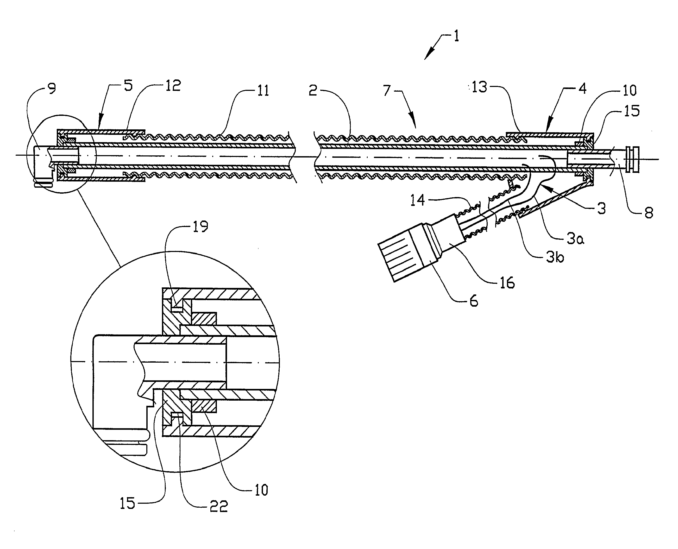
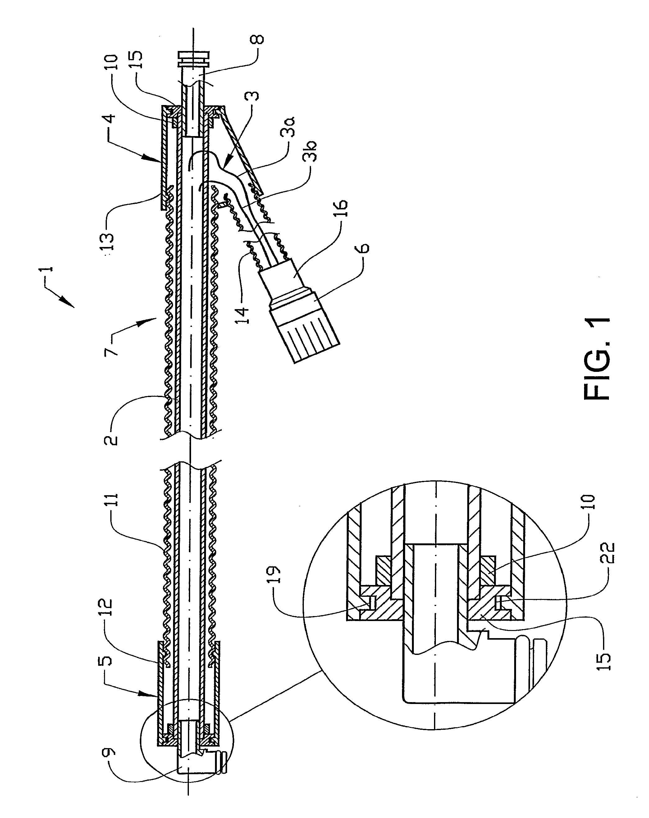
[0026]FIG. 1 shows cabling 1 according to the invention in cross-section, comprising a fluid hose 2, for example made of rubber, with integrated heating cable 3 for heating the hose 2. The hose 2 and the heating cable 3 are enclosed in a protective sheath 7. In this example, the heating cable 3 consists of two leads 3a, 3b which are embedded in the wall of the hose 2. At the first end section 4 of the cabling, the heating cable 3 is separated from the hose 2 so that it can be led to the electrical connector 6. At the other end section 5 of the cabling, the heating cable 3 is separated fro...


PUM


Abstract

Cabling for a motor vehicle includes a fluid hose, a cable for heating the fluid hose and at least one electrical connector for connecting the cable to an electrical supply, with the fluid hose and the cable being completely surrounded by an external protective sheath. It is possible to provide heated cabling, with a fluid hose and an electrical cable being completely encapsulated.

Description

[0001] The present application is a continuation of International Application PCT / SE2005 / 000284, filed Feb. 25, 2005, which claims priority to SE 0400454-5, filed Feb. 25, 2004, both of which are incorporated by reference.BACKGROUND AND SUMMARY [0002] The present invention relates to electrically eatable cabling, preferably intended to be used in vehicles. [0003] In vehicles, there are containers for fluids that are used for various functions in the vehicle. In certain cases, there is a need to. ensure that these fluids are at a particular temperature, in order for them to work in the way intended. In other cases, it is only important to ensure that the fluids do not freeze. In these cases, a fluid tank can, for example, be provided with a heating device designed to thaw the fluid when it is frozen. When the vehicle is started up, the fluid is thawed by the heating device. In order for the fluid system to function satisfactorily, the liquid in the hose leading from the fluid tank sh...

Claims


Application Information

Patent Timeline
IPC IPC(8): H01R4/60F16L11/118F16L11/127F16L11/20F16L53/38
CPCF01N2610/02F01N2610/10F16L53/008F16L11/127F01N2610/14F16L53/38F16L11/12H01R13/005
Inventor SONDEREGGER, SIGURDHENSTROM, BENGT
Owner VOLVO LASTVAGNAR AB
Why Eureka
Try Eureka