

Method of converting web or sheet material and press for applying said method
- Summary
- Abstract
- Description
- Claims
- Application Information
AI Technical Summary
Benefits of technology
Problems solved by technology
Method used
Image

Examples
Embodiment Construction
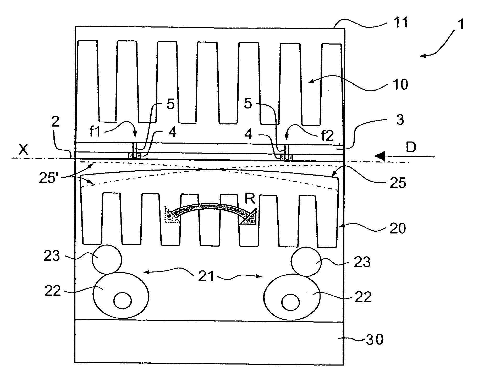
[0017] From a terminological point of view, and to avoid any confusion in the following description, the terms upstream and downstream are defined with reference to the direction of movement of the web or sheet material, as illustrated by an arrow D in the figures. This material moves from upstream to downstream following the main axis of the machine in a movement marked by periodic stops. The terms longitudinal and transverse are defined with reference to the main axis of the machine. Furthermore, in order not to overburden the description by mentioning details of construction that have no direct relevance to the invention and are well known to those skilled in the art, the terms upper table and lower table denote all those elements situated on the respective side of the material and which cooperate to convert the material.
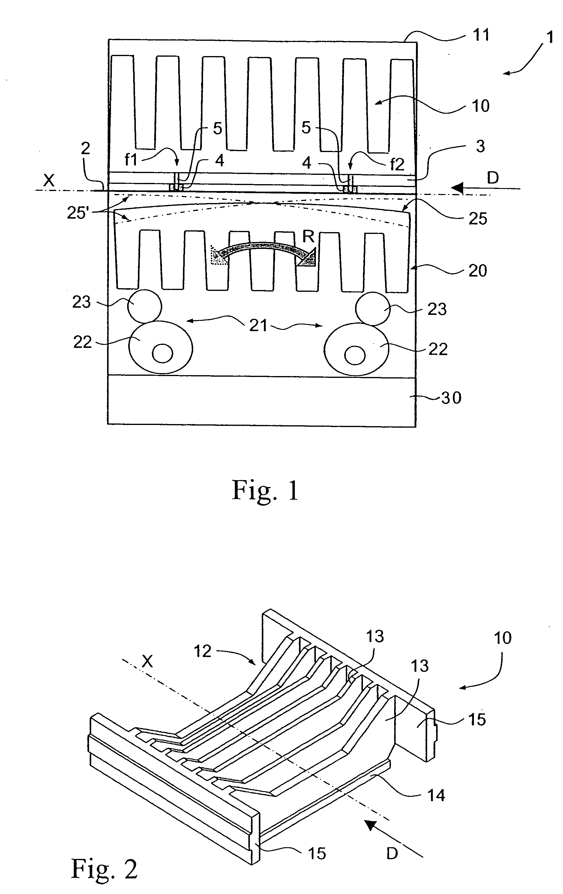
[0018]FIG. 1 shows a press 1 for processing a web or sheet material 2 traveling in the direction of movement illustrated by the arrow D. On the respective sides...
PUM
 Abstract
Description
Claims
Application Information