Variable direction of view instrument with distal image sensor

a technology of distal image sensor and variable direction, applied in the field of viewing instruments, can solve the problems of specialized expertise, system cost, and number of traditional arrangements

Active Publication Date: 2006-11-09
KARL STORZ IMAGING INC
View PDF22 Cites 25 Cited by
  • Summary
  • Abstract
  • Description
  • Claims
  • Application Information

AI Technical Summary

Benefits of technology

[0014] Accordingly, it is an object of the present invention to provide a viewing instrument having a variable direction of view that does not require a relay lens assembly.
[0015] It is a further object of the present invention to provide a viewing instrument having a variable direction of view that does not require a pivoting assembly that sweeps out a large radius.
[0016] It is yet another object of the present invention to provide a viewing instrument having a variable direction of view that does not require cabling that restricts the scan range.
[0017] It is still another object of the present invention to provide a viewing instrument having a variable direction of view that does not require a large number of optical components.

Problems solved by technology

These traditional arrangements suffer from a number of disadvantages.
First, though systems for designing, constructing, and assembling relay systems have been around for some time, these systems continue to be costly, to be time-consuming, and to demand specialized expertise.
Finally, image degradation is inevitable with such assemblies due to the fact that the light reflecting from the viewing objects must pass through a series of optical surfaces, as back-reflection, stray light, lens surface roughness, inaccuracies in lens curvatures, and slight lens misalignments all serve to reduce image quality.
However, while such distal imager designs are effective for flexible and fixed-angle rigid endoscopes, they have, thus far, not worked well for endoscopes with a variable direction of view.
Such scopes have been unable to employ a traditional optical relay system as efficiently as is possible due to the fact that, as illustrated, these scopes use movable reflecting / refracting elements to change the endoscopic line of sight, and therefore, require complex designs for the distal end of the endoscope such that the tip is capable of folding the optical path and accommodating a miniature transmission mechanism.
As a result, less room is available for an optical relay system, the performance of which decreases as its cross-section decreases.
Therefore, a variable direction of view endoscope will necessarily have an inferior image quality than a fixed-angle scope of the same diameter when employing a relay lens system.
However, as noted above, thus far, employing a distal imager in the endoscope tip (instead of using a relay system) in order to maintain good image quality has not yet been accomplished as effectively as is possible, as it has proved to be very challenging to do so while, at the same time, keeping the endoscope diameter small.
However, such pan-tilt schemes are difficult to implement compactly.
Because the solid state imaging device requires a set of lenses between the object being viewed and the image plane of the sensor, this assembly must sweep out a large radius when pivoted, which is simply too large for many endoscopic applications.
Additionally, the cabling 50 limits the available scan range.
Additionally, the mechanisms required to support and actuate such pivotable sensors require some complexity.
However, while these designs may be space-efficient, none of these devices are able to provide the same viewing versatility that is currently possible by employing a mechanism that enables a variable direction of view.

Method used


Image

  • Variable direction of view instrument with distal image sensor
  • Variable direction of view instrument with distal image sensor
  • Variable direction of view instrument with distal image sensor

Examples


Embodiment Construction

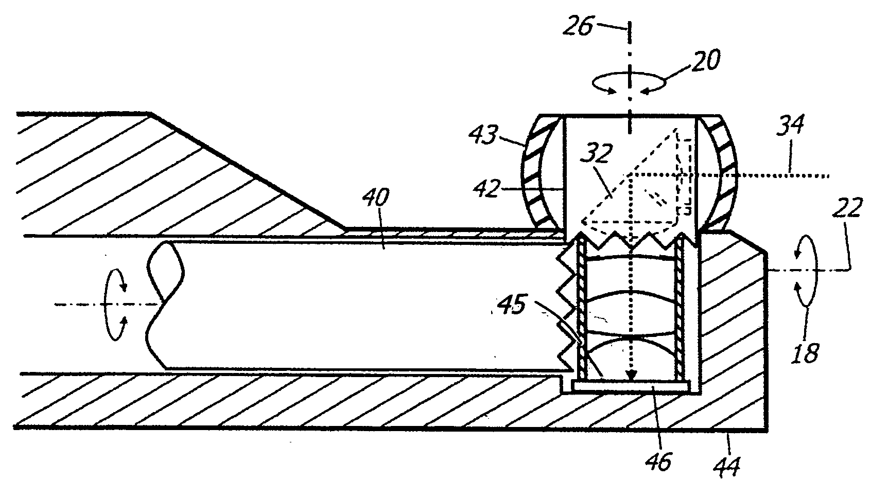
[0033] The basic components of one embodiment of a viewing instrument having a variable direction of view in accordance with the invention are illustrated in FIG. 4. As used in the description, the terms “top,”“bottom,”“above,”“below,”“over,”“under,”“above,”“beneath,”“on top,”“underneath,”“up,”“down ,”“upper,”“lower,”“front,”“rear,”“back,”“forward” and “backward” refer to the objects referenced when in the orientation illustrated in the drawings, which orientation is not necessary for achieving the objects of the invention.

[0034] The instrument includes a shaft with a distal end 44 and a longitudinal axis 22, about which the endoscope may be rotated by the user to scan along the first degree of freedom 18. An optical assembly, which includes a reflecting element 32 for folding the optical path 34 of the assembly, as well as other optical components as further described below, is located at the shaft's distal end 44.

[0035] The reflecting element 32 is rotatable about a rotational a...


PUM


Abstract

A viewing instrument having a variable direction of view is disclosed generally comprising a shaft, a sensor mounted in the distal end of the shaft such that the image plane of the sensor is substantially parallel to the longitudinal axis of the shaft, and a reflecting element that rotates about an axis substantially perpendicular to the longitudinal axis of the shaft. In some embodiments, a negative lens is mounted adjacent the reflecting element, and in certain embodiments, a positive lens is positioned adjacent the image sensor.

Description

CROSS-REFERENCE TO RELATED APPLICATIONS [0001] This patent application claims the benefit of, under Title 35, United States Code, Section 119(e), U.S. Provisional Patent Application No. 60 / 646,203, filed Jan. 21, 2005.FIELD OF THE INVENTION [0002] The present invention relates to an apparatus for obtaining wide angles of view in small areas, such as a surgical site in a patient's body. More specifically, the invention relates to a viewing instrument, such as an endoscope, with a variable direction of view and a sensor in its distal end. BACKGROUND OF THE INVENTION [0003] Viewing instruments, such as endoscopes, are generally well known in the art. Generally, an endoscope is a medical device for insertion into a body passageway or cavity that enables an operator to view and / or perform certain surgical procedures at a site inside a patient's body. As is known, endoscopes may be either rigid or flexible, and generally include a long tubular member equipped with, for example, some type ...

Claims


Application Information

Patent Timeline
Patent Type & Authority Applications(United States)
IPC IPC(8): A61B1/06A61B1/04
CPCA61B1/00096A61B1/00183A61B1/0051A61B1/05G02B26/0883G02B13/22G02B23/2423G02B23/243A61B1/051
Inventor HOEG, HANS DAVIDTESAR, JOHN C.SCHARA, NATHAN JONHALE, ERIC L.
Owner KARL STORZ IMAGING INC
Why Eureka
Try Eureka