Eureka AIR delivers breakthrough ideas for toughest innovation challenges, trusted by R&D personnel around the world.

Programmable photo power source

a photo power source and programmatic technology, applied in light therapy, radiation therapy, therapy, etc., can solve the problems of toxicity to the cell where the photosensitizers, purchase price and maintenance cost were comparatively more expensive, and achieve better irradiation results

Inactive Publication Date: 2006-11-09
LIGHTHOUSE TECH
View PDF11 Cites 34 Cited by
  • Summary
  • Abstract
  • Description
  • Claims
  • Application Information

AI Technical Summary

Benefits of technology

[0009] The primary purpose of the present invention is to provide a programmable photo power source includes an assembly of light emitting source comprised of at least two irradiation panels with each including multiple surface mounted LEDs functioning to produce a light source; a base to secure the assembly in position and a control panel is to control operation time, number of hours and current of each LED to provide better irradiation results from those surface-mounted LEDs and control of wavelength of the beam preset through the control panel as desired.

Problems solved by technology

Whereas photo power is capable of producing photochemical reaction with photosensitizer in tissue by transferring photo power to photosensitizers resulting in the singlet oxygen production that is toxic to the cell.
So far in medical phototherapy field, many light beams of given wavelength have been taken as the source to excite photosensitizers for the purpose of targeting tumor cells, and even further causing toxicity to the cell where the photosensitizers is located to achieve the purpose of tumor selectivity.
However the purchase price and the maintenance cost were comparatively more expensive and those systems introduced even earlier were too heavy to allow easy movement (The major disadvantage is the power; Because of it's high intensity irradiation, Laser may cause damage to normal cells under misoperation.).
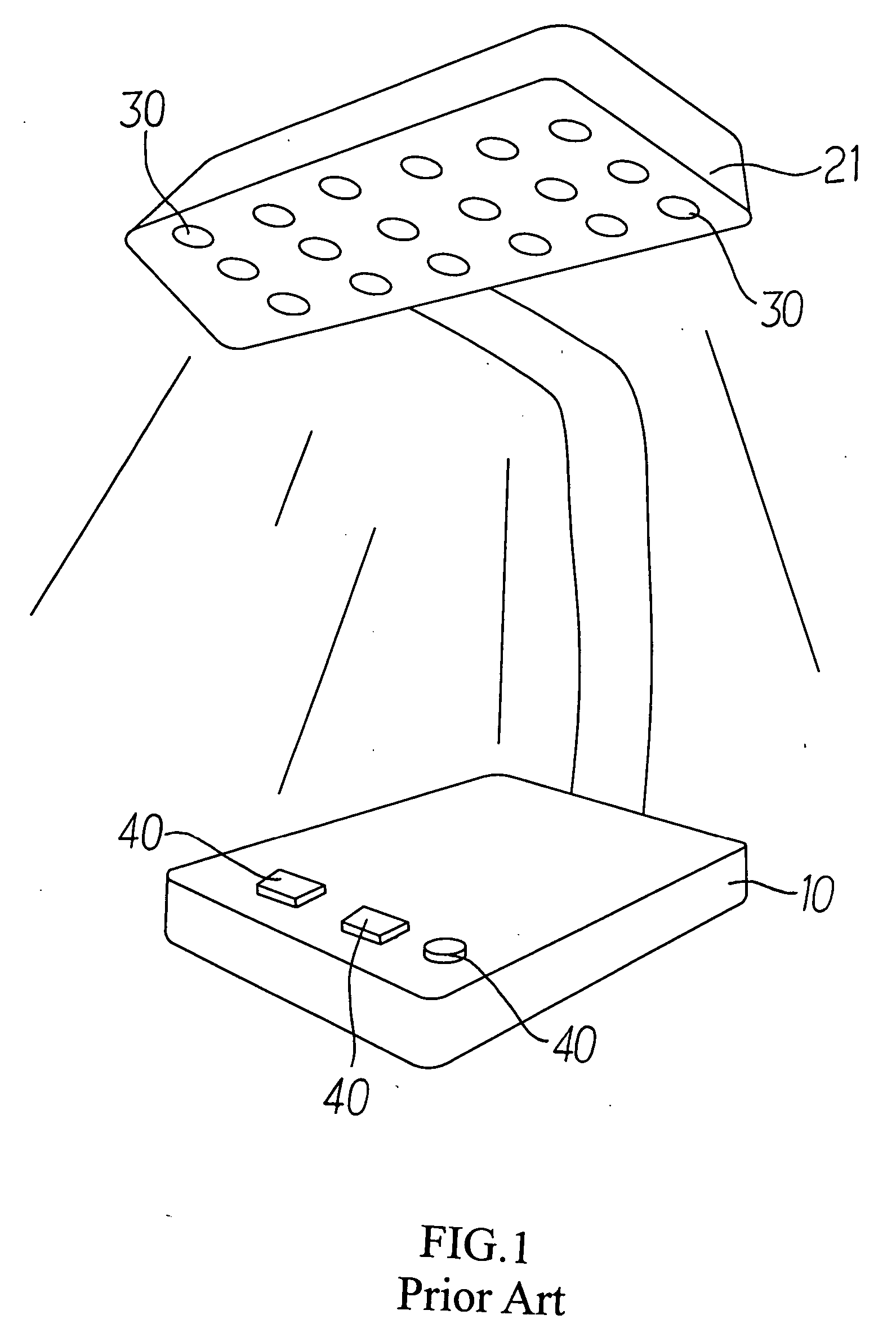
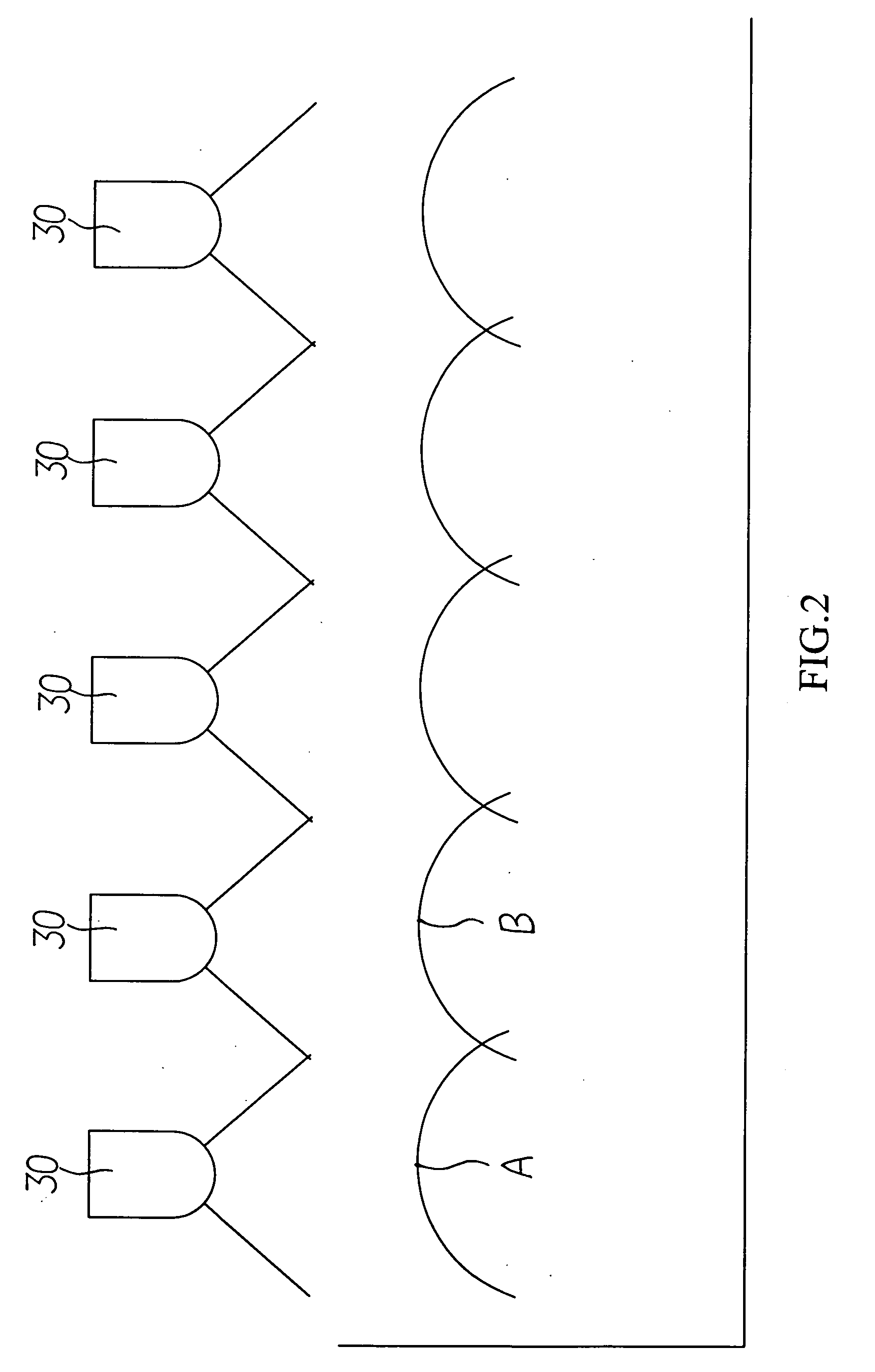
However, a significant pattern of alternatively brighter and darker areas is created due to the smaller angle of light emission by each LED bulb 30, and when mixed light is desired, the mixed light area becomes even smaller to result in poor mixing as illustrated in FIG. 2.
Most of those power sources of the prior are capable of producing only a single wavelength light source, thus their applications are limited.

Method used


Image

  • Programmable photo power source
  • Programmable photo power source
  • Programmable photo power source

Examples


Embodiment Construction

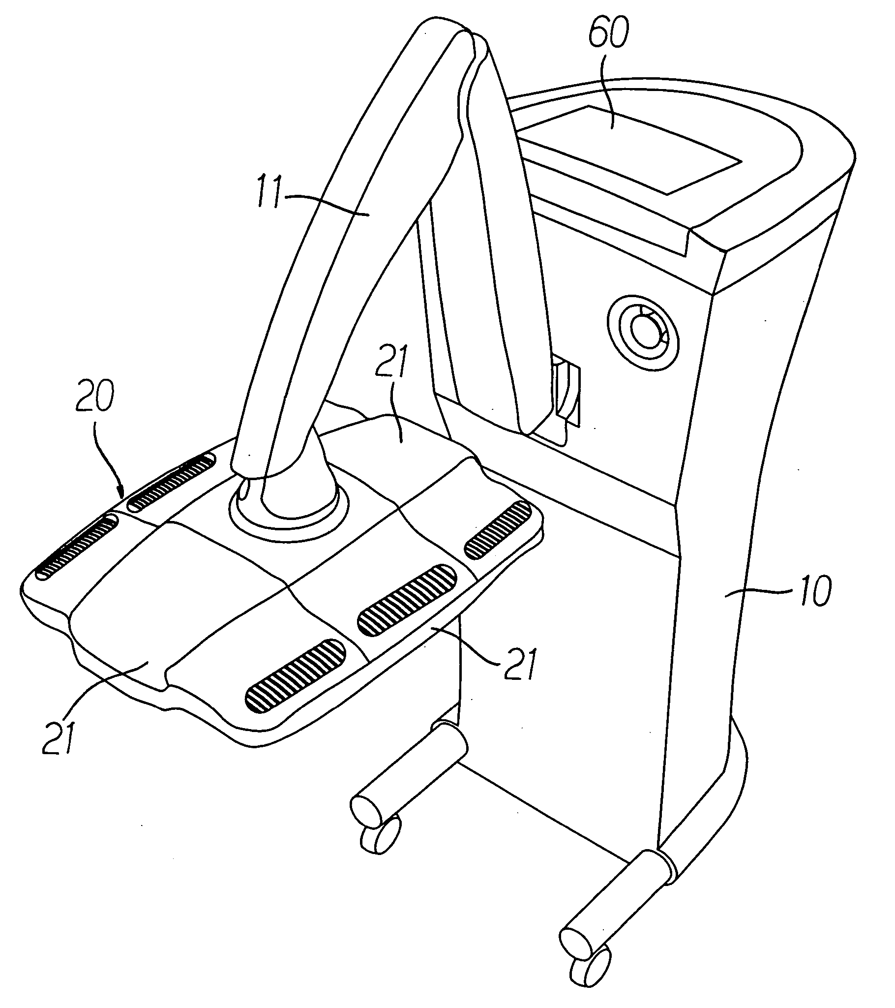
[0023] Referring to FIGS. 3 and 4 for a preferred embodiment of the present invention, a programmable photo power source is related to a light emitting source assembly 20 comprised of at least two irradiation panels 21 each including multiple surface-mounted LEDs 50 to generate light source. The assembly 20 is secured on a base 10 and adapted with a control panel 60 to control operation time, hours, current, and wavelength of each of those surface-mounted LEDs 50.

[0024] Wherein, one or multiple light emitting chip 51 is built in each LED 50 to permit any single light emitting point within the assembly 20 to provide changes in wavelength of light thus to expand the range of application for the assembly. As illustrated in FIG. 5, a reflective material 22 is provided to each irradiation panel 21 in the assembly 20 to boost the luminance of those LEDs 50. The reflective material 22 together with the inherited performance of greater light emitting angle of those LEDs 50 contributes to t...


PUM


Abstract

A programmable photo power source includes a light emitting assembly containing at least two irradiation panels foldable to each other and each comprised of multiple surface-mounted LEDs; a base to secure the assembly; and a control panel to control operation time, hours and current of each surface-mounted LED to produce better irradiation results with preset wavelength programmable through the control panel.

Description

BACKGROUND OF THE INVENTION [0001] (a) Field of the Invention [0002] The present invention is related to a programmable source to generate photo power, and more particularly, one has light emitting diode (LED) as its source of power. [0003] (b) Description of the Prior Art [0004] Whereas photo power is capable of producing photochemical reaction with photosensitizer in tissue by transferring photo power to photosensitizers resulting in the singlet oxygen production that is toxic to the cell. [0005] So far in medical phototherapy field, many light beams of given wavelength have been taken as the source to excite photosensitizers for the purpose of targeting tumor cells, and even further causing toxicity to the cell where the photosensitizers is located to achieve the purpose of tumor selectivity. Furthermore, results of studies indicate that exposure of the tissues of the wound to the the infrared laser of single wavelength radiation would help to promote healing of the wound and oth...

Claims


Application Information

Patent Timeline
Patent Type & Authority Applications(United States)
IPC IPC(8): A61N5/06A61N5/00
CPCA61N5/062A61N2005/0652A61N2005/0642A61N2005/005
Inventor FAN, CHU-PINGHSIEH, HSIANG-CHENGTSOU, SHANG-CHIH
Owner LIGHTHOUSE TECH
Why Eureka
Eureka Blog
Learn More