Moisture-barriered, body-contact protective interface structure

a protective and cushioning technology, applied in protective garments, transportation and packaging, chemistry apparatus and processes, etc., can solve problems such as discomfort, webbing system, and source of many complaints from users, and achieve unique and very effective response, reduce localized capillary circulation loss, and reduce friction

Inactive Publication Date: 2006-11-16
MJD INNOVATIONS
View PDF9 Cites 3 Cited by
  • Summary
  • Abstract
  • Description
  • Claims
  • Application Information

AI Technical Summary

Benefits of technology

[0005] The structure of the present invention offers improvements in many areas of body-protective interest. This structure, in one preferred form of the invention, features a novel, multi-layered, pad-like cushioning structure which includes different layer components that individually address (1) conformance-comfort and ballistic behaviors, (2) moisture-wicking and cooling behaviors, and (3) moisture (water)-barriering behavior that both guards and enhances the performances associated with matters (1) and (2).
[0014] The layer structure of this invention is easily rendered in a variety of specific configurations, and thus is readily usable in a host of different settings. It is relatively easy and inexpensive to manufacture, and it can be introduced very conveniently in a wide range of “retrofit” situations. The specific layer organization of the invention which is chosen for different selected applications is itself an accommodating variable—a variable which enhances the invention's versatility. For example: overall structure thickness can be different for different circumstances. A single, or more than two, rate-sensitive sublayer(s) can be employed. Within a relatively wide range, a different specific durometer value (or values) for the rate-sensitive sublayer(s) can be chosen. The moisture-wicking layer can be distributed in different ways in the structure to suit different use environments, and can be omitted if desired for use of the invention in certain applications. The moisture (water)-blocking barrier layer can have different selected characteristics to suit different applications. Importantly, this layer is chosen to be such, that in any situation, such as a water-immersion event, which exposes the proposed new layer structure to significant wetting, substantially no water can penetrate the barrier layer to degrade the shock-managing performance of the rate-sensitive layer material contained inside.

Problems solved by technology

Airspace between the webbing and the shell of the helmet greatly contributes to the ballistic and cooling capabilities of the helmet, but the webbing system has proven consistently to be quite uncomfortable, and thus to be the source of many complaints from users.
Generally speaking, such discomfort comes about principally because of localized capillary circulation loss caused by localized high-pressure points that exist in the contact interface between the helmet and the head.
These pressure points come about typically because of poor conformation (uneven pressure distribution) of the usual web-borne head-contacting structure and the shape of the head.
Such pressure points generate the complained-of discomfort and pain by creating localized low-blood-concentration ischemia regions in the head.
Notably, the structure's improved ballistic behavior remains uncompromised even in the very challenging circumstances of water immersion which can, if not carefully prevented from introducing any water into the cushioning core material, appreciably disable the shock-handling capabilities of that material.
In addition, the barrier layer is designed to accommodate substantially uncompromised cushioning behavior in the adjacent rate-sensitive, viscoelastic structure.
This material is temperature and pressure sensitive, and tends to creep (flow laterally) away from hot spots and from localized high-pressure spots.
This behavior causes a shock load to be transmitted to and borne by the body over a relatively wide surface area, and thus generally reduces the likelihood of serious injury.
Moisture infusion would dramatically and negatively affect ballistic-response cushioning behavior.

Method used


Image

  • Moisture-barriered, body-contact protective interface structure
  • Moisture-barriered, body-contact protective interface structure

Examples


Embodiment Construction

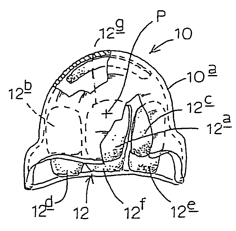
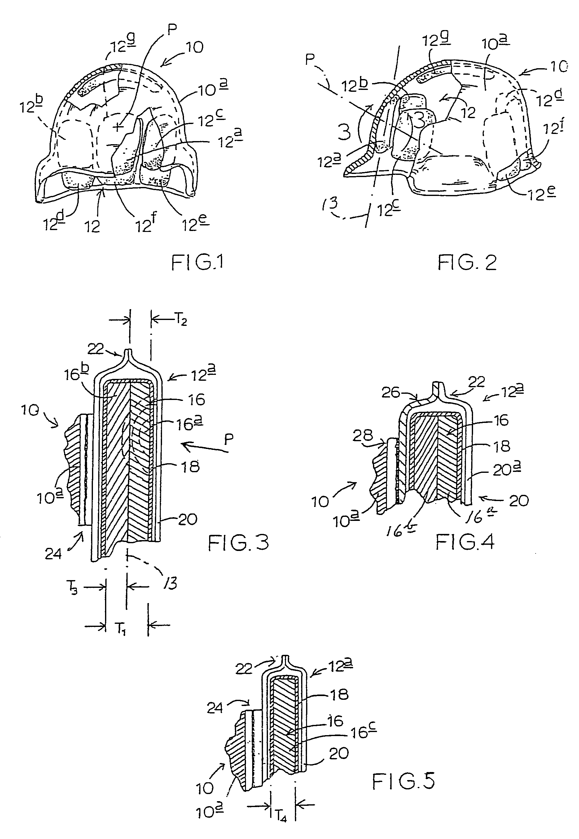
[0022] Turning attention now to FIGS. 1, 2 and 3, indicated generally at 10 (FIGS. 1 and 2) is a military helmet including a shell 10a. In all respects, shell 10a is completely conventional in construction, and might have any one of a number of different specific constructions and configurations. Fastened in a manner that will shortly be described on the inside, concave, dome-like wall of shell 10a is an installation 12 of body-contacting interface structure constructed in accordance with the present invention. Installation 12, in the particular setting illustrated in these figures and now being described, includes seven, individual, multi-layer, cushioning, interface-structure pads 12a, 12b, 12c, 12d, 12e, 12f, 12g, each of which is constructed with one preferred form of a layered-assembly organization proposed by the present invention. Each such pad is also referred to herein as a body-contacting, expanse-like cushioning structure. Pad 12a is joined to the inside wall of shell 10a...


PUM

PropertyMeasurementUnit
structureaaaaaaaaaa
viscoelasticaaaaaaaaaa
acceleration-rate-sensitiveaaaaaaaaaa

Abstract

A moisture-barriered, body-contact protective interface structure including a core, viscoelastic, acceleration-rate-sensitive cushioning structure, and a moisture-barriering container surrounding the cushioning structure, with the container being operable to block the flow of moisture while accommodating gas breathability for the cushioning structure.

Description

CROSS REFERENCES TO RELATED APPLICATIONS [0001] This application is a continuation from U.S. patent application Ser. No. 10 / 156,074, filed May 27, 2002, for “Body-Contact Protective Interface Structure and Method”, which is a continuation from U.S. patent application Ser. No. 09 / 942,987, filed Aug. 29, 2001, entitled “Body-Contact Cushioning Interface Structure and Method”, which is a continuation from U.S. patent application Ser. No. 09 / 390,518, filed Sep. 3, 1999, entitled “Body-Contact Cushioning Interface Structure”, which application claims priority to U.S. Provisional Application Ser. No. 60 / 099,208, filed Sep. 3, 1998, entitled “Body Contact System and Structure for Wearable Garments, such as a Helmet.”BACKGROUND AND SUMMARY OF THE INVENTION [0002] The present invention relates to a human-body-contact, protective and cushioning interface structure. More particularly, it relates to such a structure which is designed to be interposed the body and some external structure which i...

Claims


Application Information

Patent Timeline
Patent Type & Authority Applications(United States)
IPC IPC(8): A42B3/00A42B3/12B32B3/26B32B25/08B32B33/00
CPCA42B3/12A42B3/121A42B3/125B32B33/00B32B3/26B32B25/08A42B3/127Y10T428/249953B32B2307/724B32B2437/04B32B2307/7246
Inventor DENNIS, MICHAEL R.TUCKER, MICHAEL W.PAASCHE, GERHARD
Owner MJD INNOVATIONS
Why Eureka
Try Eureka