Continuous adhesive roller

a technology of adhesive rollers and rollers, which is applied in the direction of vehicle maintenance, vehicle cleaning, cleaning equipment, etc., can solve the problems of lint, dust and other debris that cannot be used continuously over a surface, the device cannot be utilized to make multiple passes or swipes over a surface, and the number of uses of the roller is limited

Active Publication Date: 2006-11-16
SC JOHNSON & SON INC
View PDF68 Cites 15 Cited by
  • Summary
  • Abstract
  • Description
  • Claims
  • Application Information

AI Technical Summary

Benefits of technology

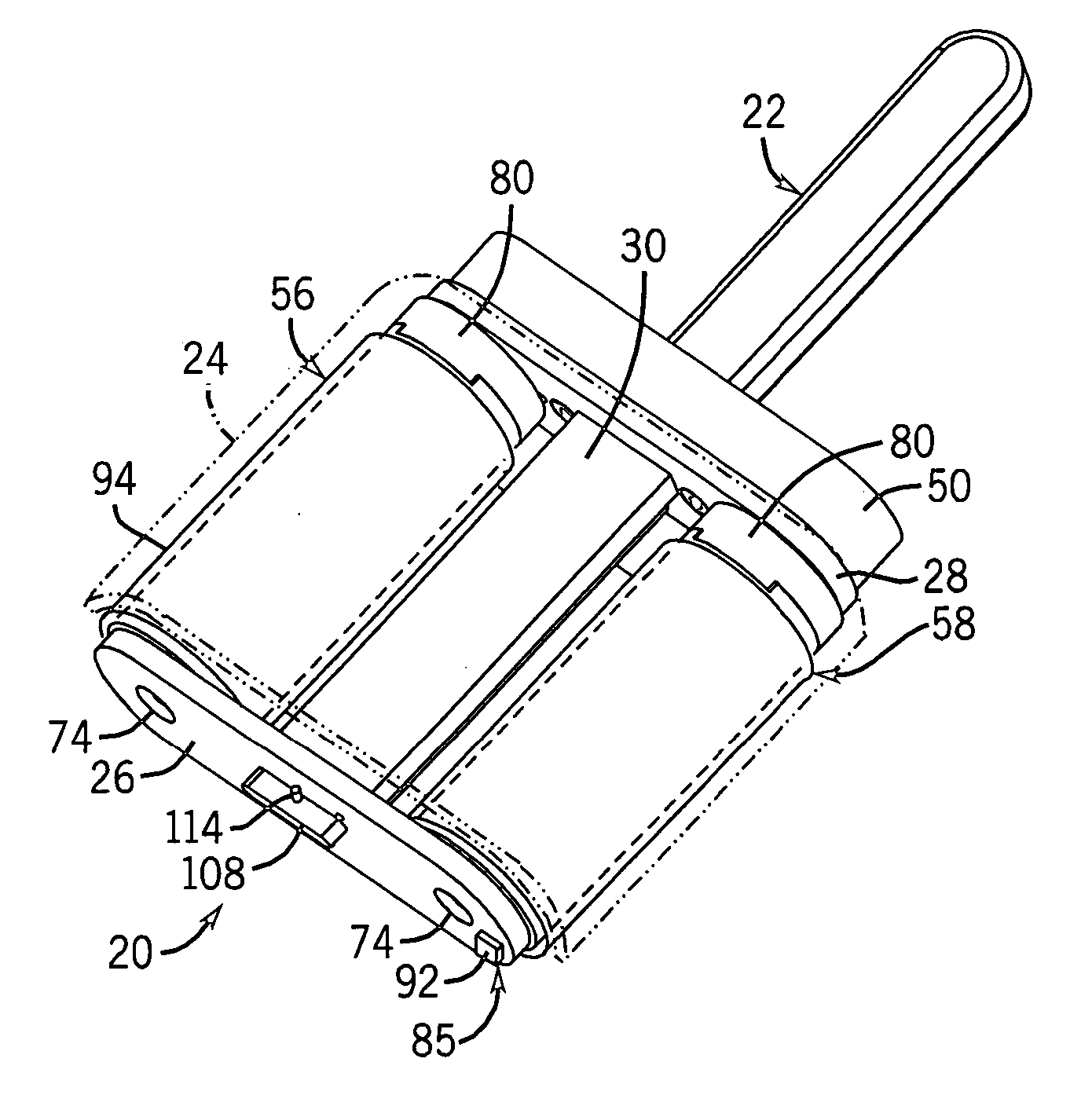
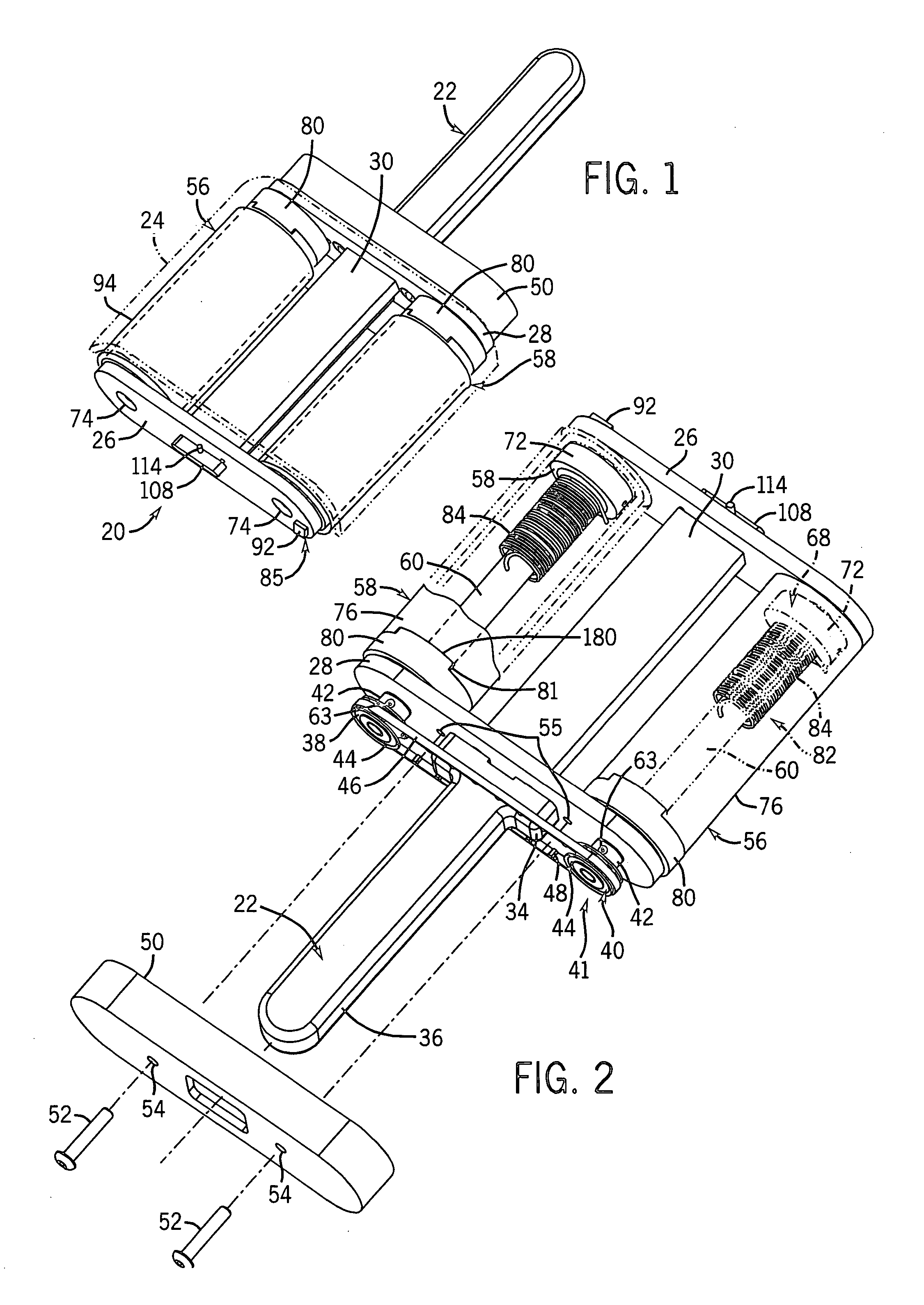
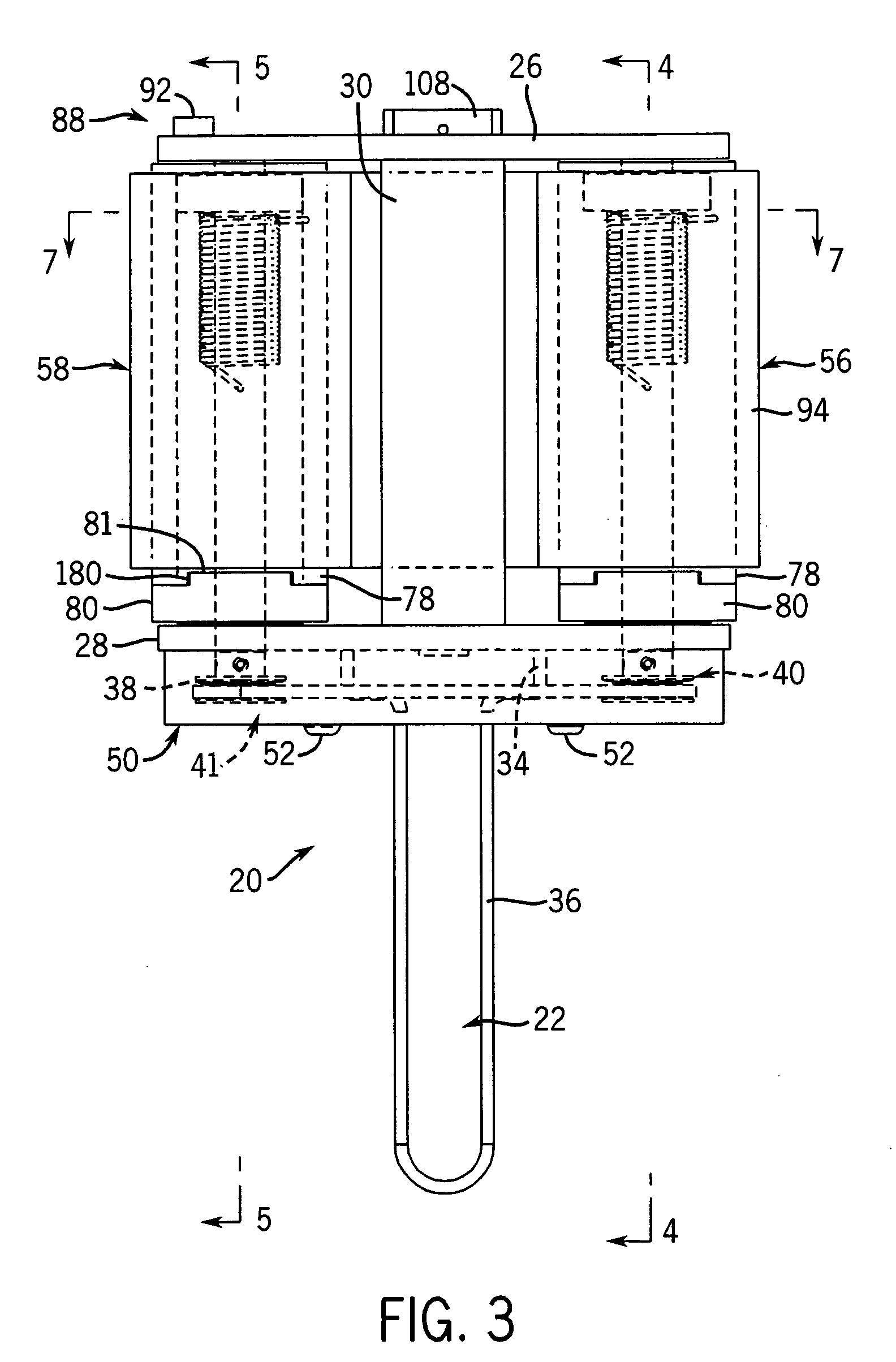
[0011] According to one aspect of the present invention, a continuous adhesive roller cleaning device is provided in which a supply roller and a take-up roller are rotatably mounted to a hand held housing. One or both of the rollers includes a biasing mechanism that provides tension on a web of an adhesive material extending between the rollers such that the web properly contacts the surface to be cleaned when the device is in use. The biasing mechanism roller(s) biases or tensions the roller(s) at different levels, such that the take-up roller has a spring force greater than that for the supply roller. A braking mechanism is engaged with one of the rollers in order to create generally equal forces acting on the supply roller and the take-up roller while the device is in use. Deactivation of the braking mechanism allows the increased spring force acting on the take-up roller to draw the web of adhesive sheet material off of the supply roller, thereby advancing the web a selected amount to provide a clean, unused section of the web for continued use of the device.

Problems solved by technology

However, with regard to cleaning devices of this type, the roller has a limited number of uses.
However, the rollers do not allow for the web to move continuously between the rollers when the device is in use, such that the device cannot be moved continuously over a surface to pickup lint, dust and other debris from the surface.
However, in each of the prior art devices including a supply roller and a take-up roller supporting an adhesive material web, the mechanisms for advancing the web of adhesive material allows for the advancement of material substantially in one direction, such that the devices cannot be utilized to make multiple passes or swipes over a surface to provide enhanced cleaning of the surface.
Also, the prior art devices do not illustrate mechanisms for controlling the rotation of the supply end and take-up rollers that can accommodate the changing amounts of the web disposed on each roller, and the corresponding changing rotational speeds of the rollers, to keep the web properly tensioned at all times.

Method used


Image

  • Continuous adhesive roller
  • Continuous adhesive roller
  • Continuous adhesive roller

Examples


fourth embodiment

[0069] Referring now to FIGS. 11-15, a fourth embodiment for the device 200 includes a housing 202 having an upper surface 204 and a pair of downwardly extending side panels 206 and 208. The housing 202 also includes a handle 205 that is positioned on the upper surface 204 between the side walls 206, 208 to extend generally parallel to the side walls 206, 208. The handle 205 can have any desired shape or configuration, e.g., the handle can also be oriented perpendicular to the walls 206, 208, but in this embodiment takes the form of a generally U-shaped bar connected to the surface 204 at opposite ends and defining a space 207 between the handle 205 and the surface 204.

[0070] Within the housing 202, a roller mechanism 209 is disposed which includes a pair of plates 210, 212, which are generally triangular in shape but which can have any shape desired or required, that are releasably secured to and extend parallel to the side walls 206 and 208. One plate 210 includes a synchronizatio...

fifth embodiment

[0072] Referring now to FIGS. 16-22, a fifth embodiment for the device 200 is illustrated in which only a single idler roller 214 is rotatably positioned between the supply roller 56 and the take-up roller 58. The take-up roller 58 is also moved forwardly within the housing 202 towards the supply roller 58 in order to provide a generally planar contact surface section for the web 94 between the idler roller 214 and the take-up roller 58. The plates 210, 212 are also shown to have multiple bores 220 in which the take-up roller 58 and idler rollers 214, 216 can be mounted to form the various embodiments for the device 200, as well as a pair of mounting openings 222, used to releasably secure the plates 210, 212 within the housing 202. A pair of supports 224, 226 is also shown extending between the plates 210, 212 to provide stability to and ensure proper connection between the rollers 56, 58, 214 and the plates 210, 212.

[0073] A sixth embodiment for the device 200 is illustrated in FI...


PUM


Abstract

A device (20) for cleaning surfaces is provided utilizing a web (94) of a tackified sheet material movably secured between rollers (56, 58) on the device (20) that enable the web (94) to be moved over the surface in opposite directions. The device (20) includes a supply roller (56) and a take-up roller (58) secured to opposed ends of the web (94) of adhesive sheet material, with at least one roller (56, 58) including a biasing mechanism (82) disposed within the roller (56, 58). The web (94) can be engaged with the surface by passing over a number of idler rollers (98) positioned between the supply roller (56) and take-up roller (58). The biasing mechanism (82) is designed to bias the movement of the web (94) onto the take-up roller (58), such that the mechanism (82) can be selectively operated to advance the web (94) from the supply roller (56) to the take-up roller (58) to expose a clean section of the adhesive sheet material (94). A synchronization mechanism (41) is also connected between the rollers (56, 58) to enable the rollers (56, 58) to rotate in a synchronous manner, regardless of the amount of the web (94) that is positioned on the rollers (56, 58) to continually tension the web (94) a proper amount. The device (20) also is designed to enable the supply roller (56) and take-up roller (58) to be removed as a unit for replacement and disposal after the entire length of the web (94) of adhesive sheet material has been utilized to clean a surface or surfaces. The rollers (56, 58) can be disposed within a housing (50, 202) having a handle (22, 205) thereon to facilitate use of the device (20). The handle (22, 205) can extend from one side of the housing (50) or can be secured to top surface of the housing (202).

Description

CROSS-REFERENCE TO RELATED APPLICATIONS [0001] This application claims priority U.S. Provisional Patent Application Ser. No. 60 / 672,156, filed on Apr. 15, 2005, and U.S. Provisional Patent Application Ser. No. 60 / 692,411, filed on Jun. 21, 2005, the entities of which are expressly incorporated by reference herein in their entirety.FIELD OF THE INVENTION [0002] The present invention relates to surface cleaning devices, and more specifically to a surface cleaning device including rollers on which are movably disposed a continuous adhesive web or sheet utilized to pick up dust, lint and other debris from the surface. BACKGROUND OF THE INVENTION [0003] A number of different surface cleaning devices utilizing adhesive sheets or webs have been developed for cleaning various surfaces. The majority of these devices include a single roller having a sheet of material with a tackified outer surface disposed on the exterior of the roller that is capable of picking up lint, dust and other debris...

Claims


Application Information

Patent Timeline
Patent Type & Authority Applications(United States)
IPC IPC(8): B60S1/02
CPCB08B7/0028A47L25/005
Inventor KNOPOW, JEREMY F.ZACH, STEVEN A.MALONEY, MICHAEL J.MICK, JONATHAN M.ASKLING, KEVIN L.SUTRINA, THOMAS A.
Owner SC JOHNSON & SON INC
Why Eureka
Try Eureka