Calibration method for a parallel kinematic mechanism machine

a kinematic mechanism machine and calibration method technology, applied in mechanical measuring arrangements, instruments, manufacturing tools, etc., can solve the problems of difficult to eliminate geometrical errors, inability to accurately estimate kinematic parameters, and time-consuming attachment and detachment of supporting units, so as to improve the geometric accuracy of motion of the end effector and achieve high precision. , the effect of high precision

Inactive Publication Date: 2006-11-16
OKUMA CORP
View PDF4 Cites 24 Cited by
  • Summary
  • Abstract
  • Description
  • Claims
  • Application Information

AI Technical Summary

Benefits of technology

[0020] According to this method, by using a ball plate as a jig, reproduction error due to attachment and detachment of components can be completely eliminated and the working time therefor is unnecessary. As a result, calibration can be performed in a short time with high precision.
[0021] According to the present invention, since error factors other than kinematic parameters, for example, deformation error caused by self-weight, thermal displacement of each component, and error of a measuring device, are added for computation, calibration can be performed by precisely estimating the kinematic parameters. As a result, geometric accuracy of motion of the end effector can be improved.
[0022] In addition, by using a ball plate, reproduction error due to attachment and detachment of the supporting unit can be completely eliminated and the working time therefor is unnecessary. As a result, calibration can be performed in a short time with high precision.

Problems solved by technology

In an operating machinery such as a machine and a robot, it is difficult to eliminate geometrical error when a position and a posture of an end effector such as a main spindle, a tool, and a hand, are controlled.
On the other hand, there is a problem that a measured value by the DBB measuring method includes error caused by factors other than kinematic parameters, so that it is impossible to accurately estimate the kinematic parameters.
However, when the DBB measuring method disclosed in Japanese patent publication of unexamined application No. 2005-103720 is applied to a parallel kinematic mechanism machine, DBB measuring at plural positions is required, whereby a supporting unit with a fixed ball needs to be attached and detached repeatedly.
Consequently, it takes time to attach and detach the supporting unit.
Moreover, there is a problem that a precise calibration is impossible because of various factors, for example, reproducibility in repeated attachment and detachment, and thermal displacement of a machine accompanied by environmental temperature change due to elapsed time.
In addition, a measured value obtained by DBB measuring includes thermal displacement of components, error of the DBB bar length, and error of the ball diameter other than the deformation error caused by self-weight of the component of the machine.
Therefore, taking into consideration deformation error caused by self-weight of the component only is not sufficient to estimate the kinematic parameters precisely.

Method used


Image

  • Calibration method for a parallel kinematic mechanism machine
  • Calibration method for a parallel kinematic mechanism machine
  • Calibration method for a parallel kinematic mechanism machine

Examples


Embodiment Construction

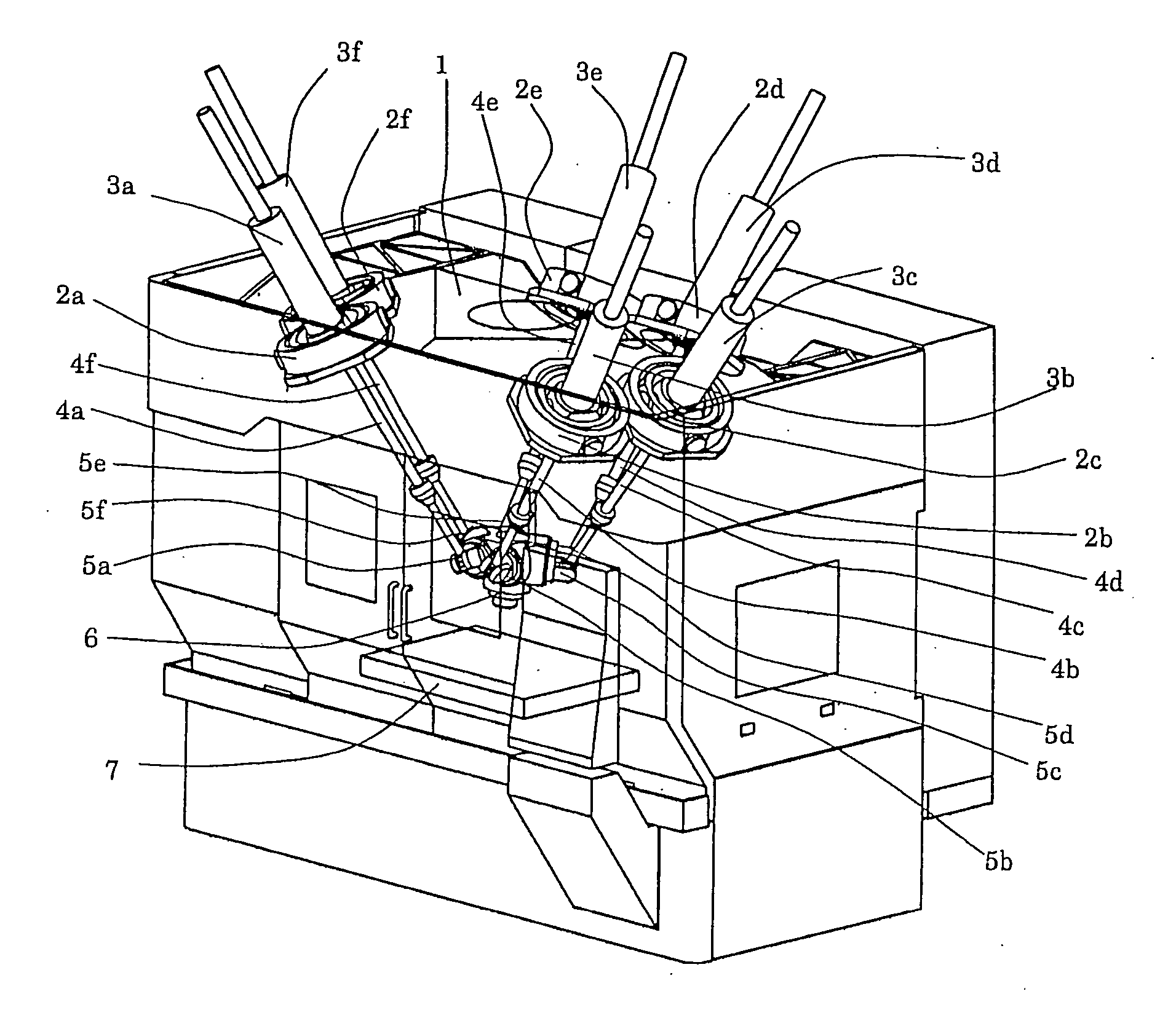
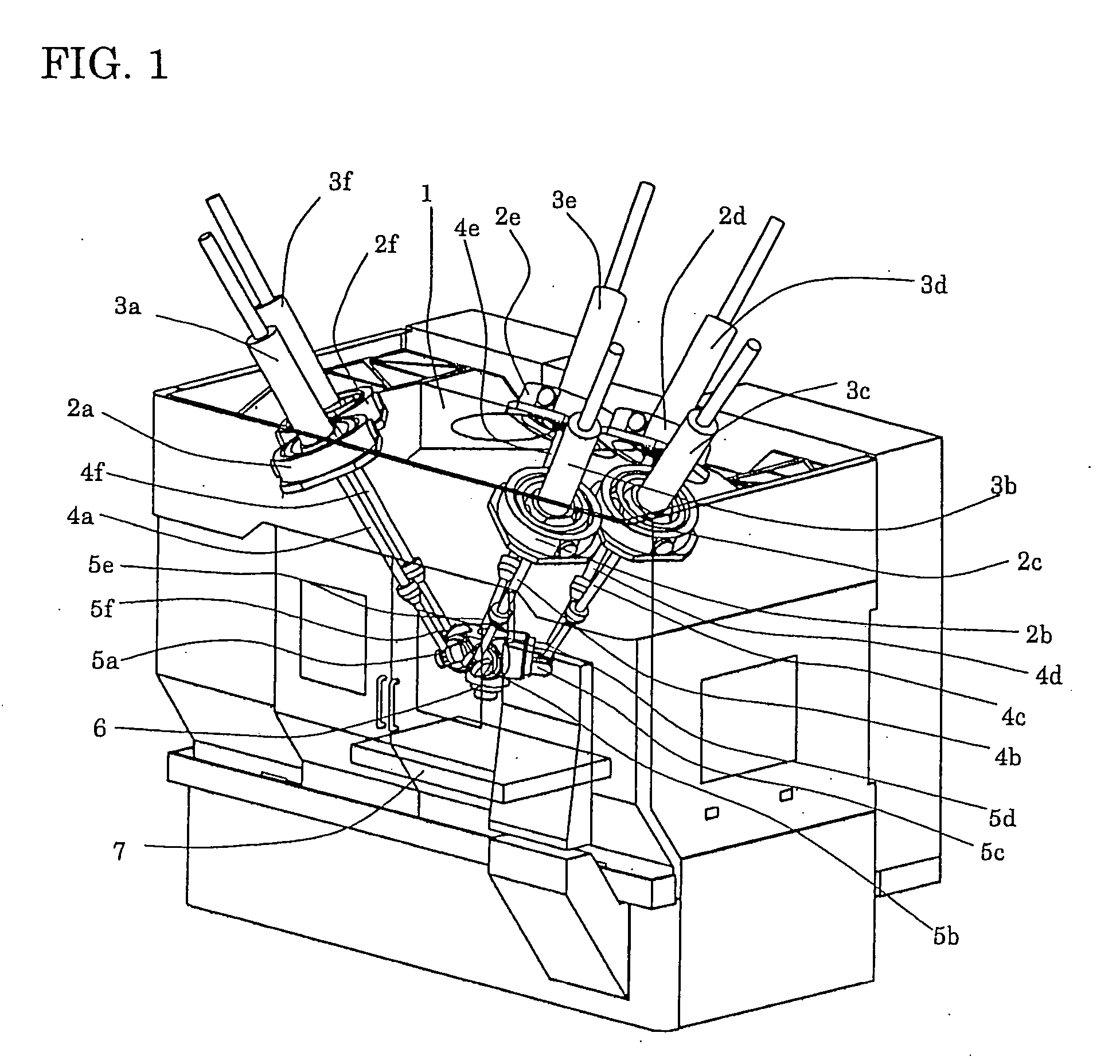
[0028] Hereinafter, the preferred embodiment of the present invention will be explained in detail with reference to the drawings. FIG. 1 shows a Stewart-platform parallel kinematic mechanism machine tool with six degrees of freedom, which is one of parallel kinematic mechanism machines. The parallel kinematic mechanism machine tool comprises a frame 1 fixed on a floor, six first universal joints 2a to 2f attached to the frame 1, servomotors 3a to 3f connected to first universal joints 2a to 2f respectively, ball screws 4a to 4f driven respectively by the servomotors 3a to 3f, second universal joints 5a to 5f connected to the lower ends of ball screws 4a to 4f respectively, one end effector 6 having second universal joints 5a to 5f, a table 7 fixed on the frame 1 on the opposite side of the end effector 6.

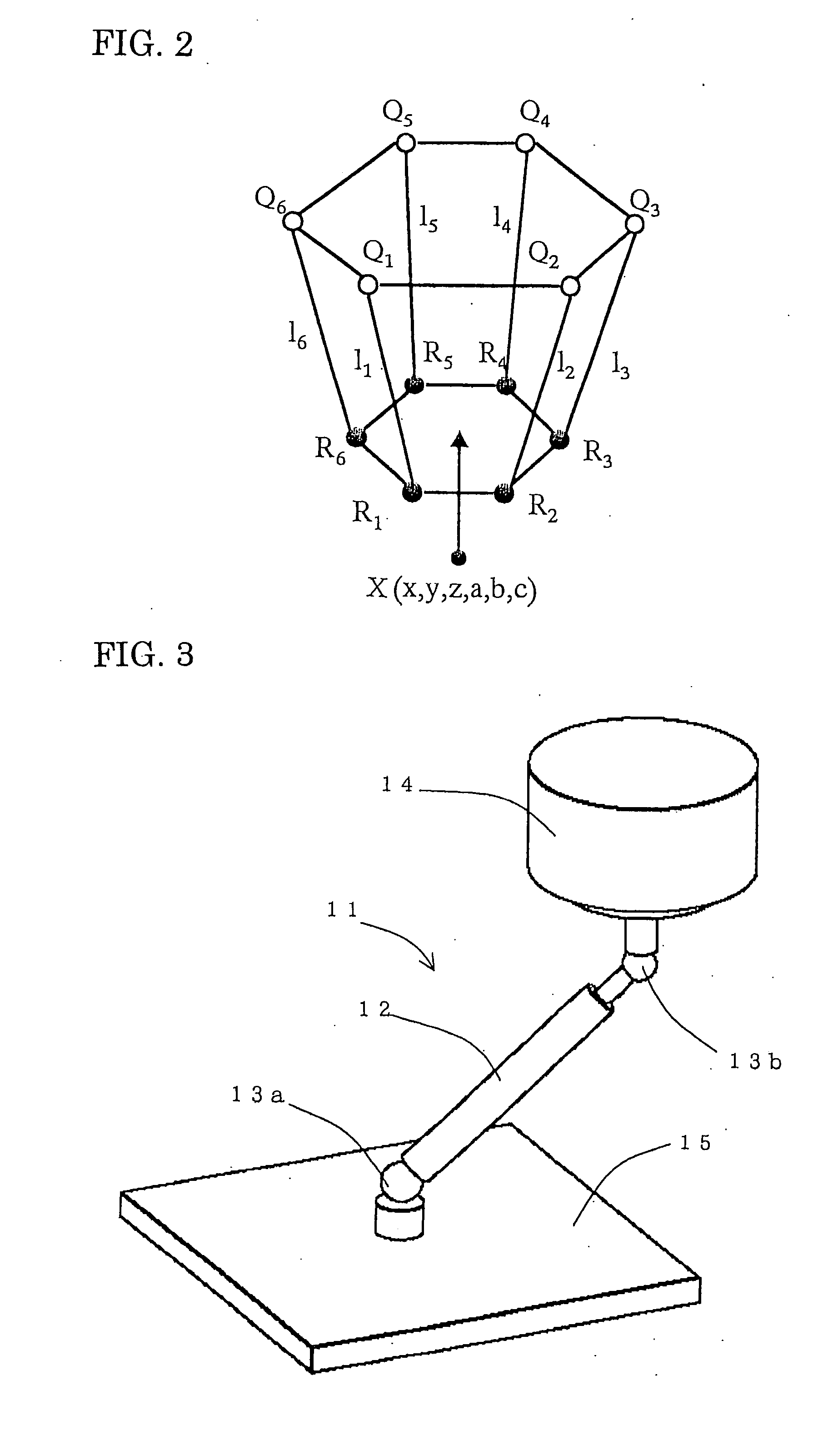
[0029] As shown in a frame format of FIG. 2, there are 42 parameters as kinematic parameters, which are, positions of rotating center of base joints Q1-Q6 and end effector joints R...


PUM


Abstract

Kinematic parameters of a parallel kinematic machine can be estimated with high precision considering thermal displacement and error of a measuring device, in addition to deformation error caused by self-weight of each component. A DBB device is used when end effectors of a parallel kinematic mechanism machine are positioned at plural positions and in plural postures. In the DBB device, a plurality of support bars are provided with rigid balls on the both ends. One of the balls is fixed on a table and the other ball is provided with an end effector. The position, posture, and distance from a fixed position are measured and based on the measured value kinematic parameters are estimated. In estimating the kinematic parameters, any of deformation error caused by self-weight of each component, thermal displacement of each component, error of a measuring device are added for computation by linear approximation.

Description

BACKGROUND OF THE INVENTION [0001] This application claims the benefit of Japanese Patent Application Number 2005-143175 filed on May 16, 2005, the entirety of which is incorporated by reference. [0002] 1. Field of the Invention [0003] The present invention relates to a method for correcting error of an end effector in an operating machinery such as a machine with a parallel kinematic mechanism and a robot. [0004] 2. Description of the Related Art [0005] In an operating machinery such as a machine and a robot, it is difficult to eliminate geometrical error when a position and a posture of an end effector such as a main spindle, a tool, and a hand, are controlled. In order to deal with this, a method is proposed which corrects error by calibrating kinematic parameters. As a calibration method, there is a so-called Double Ball Bar(DBB) measuring method, where displacement of a support bar with balls attached at the both ends is measured and error of the kinematic parameters is estimat...

Claims


Application Information

Patent Timeline
Patent Type & Authority Applications(United States)
IPC IPC(8): G01B5/30G01B7/16
CPCB25J9/1692B25J9/1623
Inventor MATSUSHITA, TETSUYA
Owner OKUMA CORP
Why Eureka
Try Eureka