Internal combustion engine comprising a mechanical charger and a turbo-compound

Inactive Publication Date: 2006-11-16
DAIMLER AG
View PDF6 Cites 19 Cited by
  • Summary
  • Abstract
  • Description
  • Claims
  • Application Information

AI Technical Summary

Benefits of technology

[0021] In a further embodiment of the invention, the exhaust gas turbine has a waste gate. The internal combustion engine has an exhaust system in addition to the mechanical charger and to the turbo-compound. The exhaust system is arranged downstream of the exhaust gas turbine of the turbo-compound. The exhaust system has, inter alia, a catalytic converter. The waste gate has a controllable bypass in a casing of the exhaust gas turbine. In the open position of the waste gate, the exhaust gas bypasses the exhaust gas turbine, so that the exhaust gas turbine is not driven by the exhaust gas of the internal combustion engine. By the exhaust gas turbine being bypassed, the exhaust gas back pressure falls and the efficiency of the internal combustion engine rises. Moreover, in the case of a cold start, the exhaust gas temperature can be held at a high level. This leads advantageously to a rapid heating of the catalytic converter. In a closed position of the waste gate, the exhaust gas flows through the exhaust gas turbine. The energy content of the exhaust gas thereby falls, thus leading to a lower exhaust gas temperature and reducing the pulsations of the exhaust gas. This advantageously gives rise to a careful treatment of the catalytic converter. Particularly in operating states of the internal combustion engine in which

Problems solved by technology

The power consumed by the mechanical charger, which needs to be pro

Method used


Image

  • Internal combustion engine comprising a mechanical charger and a turbo-compound
  • Internal combustion engine comprising a mechanical charger and a turbo-compound
  • Internal combustion engine comprising a mechanical charger and a turbo-compound

Examples


Embodiment Construction

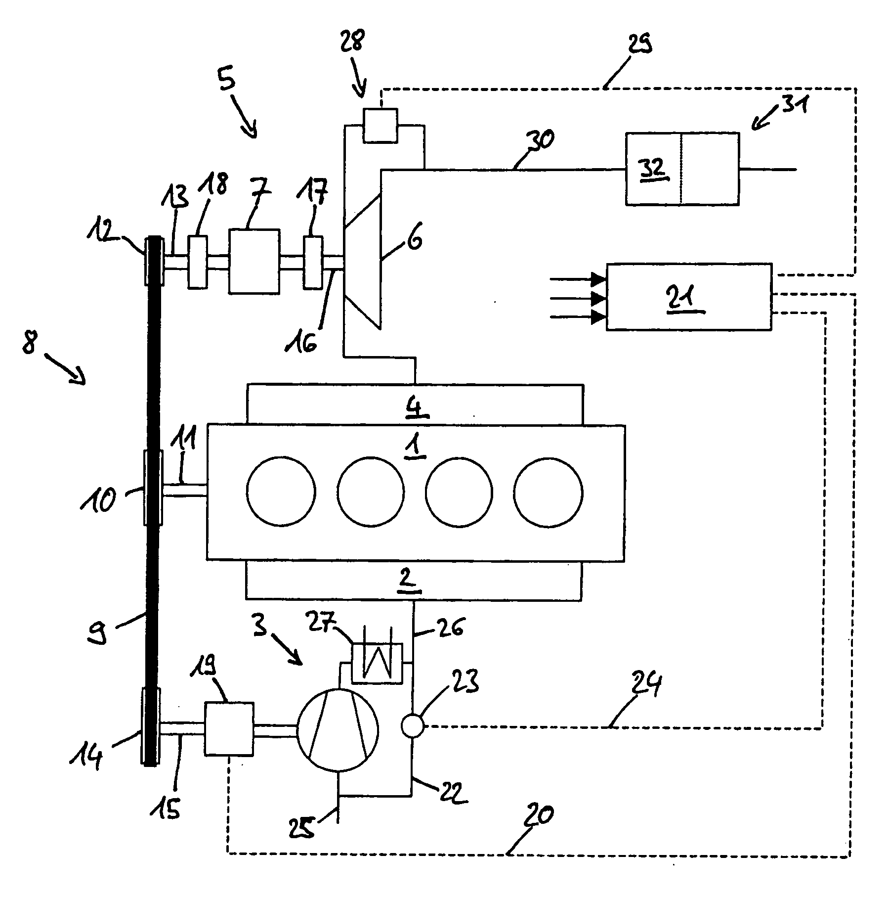
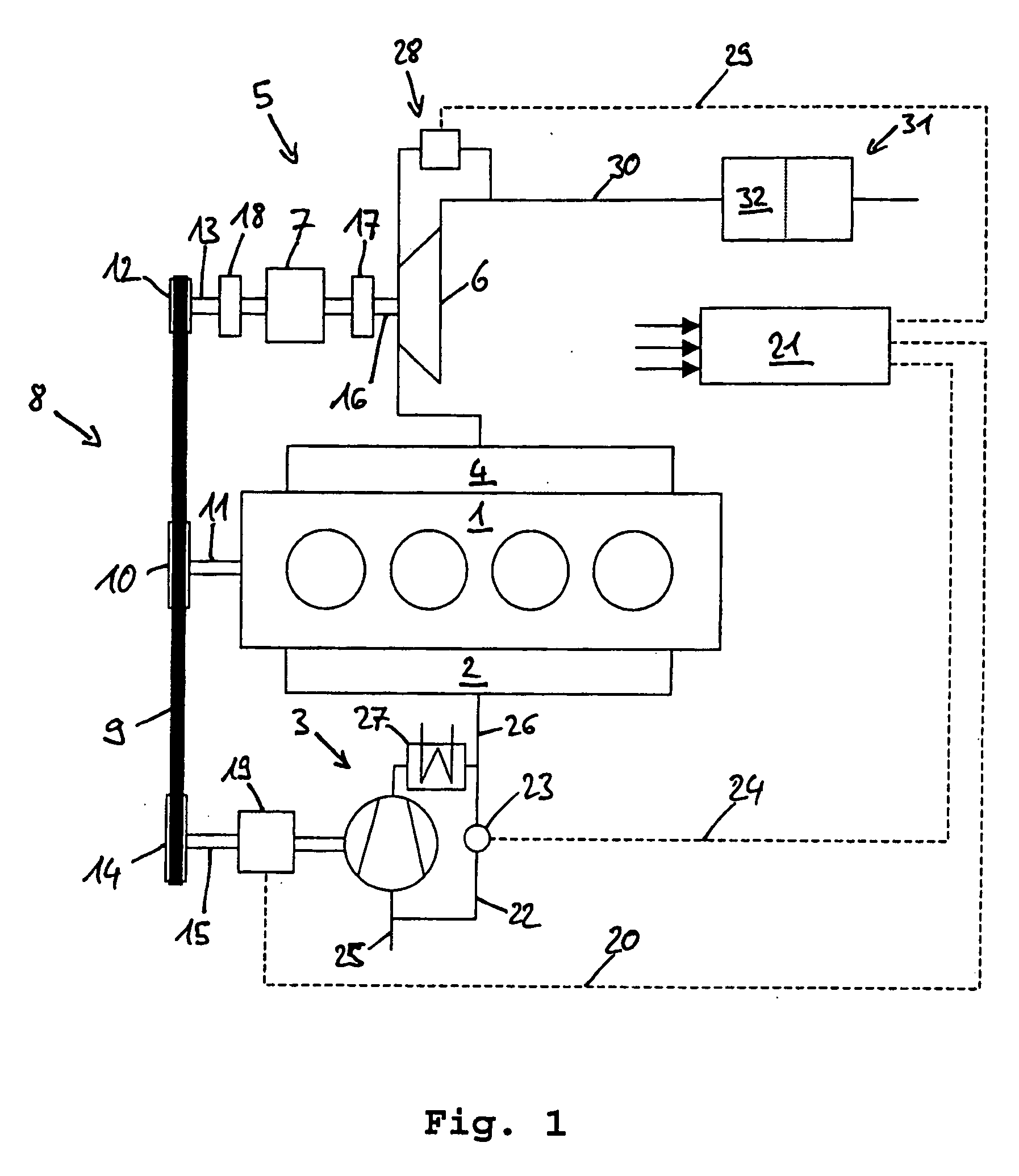
[0027]FIG. 1 illustrates a first version of the internal combustion engine 1 according to the invention. The internal combustion engine 1 is preferably a spark ignition engine for passenger cars. However, use for diesel engines, in particular for commercial vehicles, may also be envisaged. The internal combustion engine 1 has an inlet tract 2 and, assigned to this, a mechanical charger 3 and an outlet tract 4 and, assigned to this, a turbo-compound 5. The turbo-compound 5 has an exhaust gas turbine 6 and a reduction gear 7 coupled to the exhaust gas turbine 6. The internal combustion engine 1, the mechanical charger 3 and the turbo-compound 5 are coupled to one another by means of a belt drive 8. The belt drive 8 includes a belt 9, with a belt pulley 10 on a crankshaft 11 of the internal combustion engine 1, a belt pulley 12 on an output shaft 13 of the reduction gear 7 and a belt wheel 14 on a drive shaft 15 of the mechanical charger 3.

[0028] The exhaust gas turbine 6 is coupled t...


PUM


Abstract

In an internal combustion engine comprising a mechanical charger in the form of a positive displacement compressor connected to the engine intake duct for supplying compressed air to the engine and a turbo-compound including an exhaust gas turbine connected to the engine exhaust duct for converting energy remaining in the exhaust gas to power, the exhaust gas turbine being connected to the engine via a reduction gear drive, the mechanical charger and the turbo-compound are coupled to the engine by a common belt drive including a first belt pulley mounted on the crankshaft of the engine, a second belt pulley mounted on the shaft of the reduction gear drive, and a third belt pulley mounted on the shaft of the mechanical charger.

Description

[0001] This is a Continuation-In-Part Application of International Application PCT / EP2004 / 012404 filed Nov. 3, 2004 and claiming the priority of German Application 103 55 563.3 filed Nov. 28, 2003.BACKGROUND OF THE INVENTION [0002] The invention relates to an internal combustion engine comprising a mechanical charger and an exhaust gas turbine coupled to the engine for transmitting power thereto. [0003] Internal combustion engines comprising a mechanical charger and a turbo-compound consisting of an exhaust gas turbine and a reduction gear have been known in the prior art for a long time. The mechanical charger is coupled to the internal combustion engine and compresses the air required for combustion. The turbo-compound utilizes the energy contained in the exhaust gas of the internal combustion engine by means of the exhaust gas turbine and transmits the power obtained from the exhaust gas to the internal combustion engine via a reduction gear. [0004] Particularly positive displace...

Claims


Application Information

Patent Timeline
IPC IPC(8): F02B33/00F02B33/36F02B37/00F02B37/10F02B37/16F02B37/18F02B39/04F02B39/08F02B39/12F02B41/10F02B67/06
CPCF02B33/36F02B37/005F02B37/105F02B37/16F02B37/18Y02T10/163F02B39/08F02B39/12F02B41/10F02B67/06Y02T10/144F02B39/04Y02T10/12
Inventor BOTTCHER, MICHAELENDERLE, CHRISTIANHUFENDIEK, JOCHENWUNDERLICH, KLAUS
Owner DAIMLER AG
Why Eureka
Try Eureka