Injection molding apparatus

Inactive Publication Date: 2006-11-16
YKK CORP
View PDF5 Cites 53 Cited by
  • Summary
  • Abstract
  • Description
  • Claims
  • Application Information

AI Technical Summary

Benefits of technology

[0011] The present invention has been made in view of the prior art described above and its fundamental object is to provide an apparatus capable of producing a high-quality molded article, in which a melt of a metal which has been heated and melted hardly flows into a gap

Problems solved by technology

However, since in the conventional vacuum injection molding machine cooling of the plunger or sleeve is not performed, there is a high possibility that molten metal will flow into a small gap between the inner surface of the sleeve and the side of the plunger (piston) during injection and solidify therein.
Consequently, the frictional resistance increases, and at the worst the plunger will become the immovable state within the sleeve and cannot effect injection.
When ceramic is used for the sleeve which requires heat resistance, there is a possibility that the sleeve itself may be destroyed due to the res

Method used


Image

  • Injection molding apparatus
  • Injection molding apparatus
  • Injection molding apparatus

Examples


Embodiment Construction

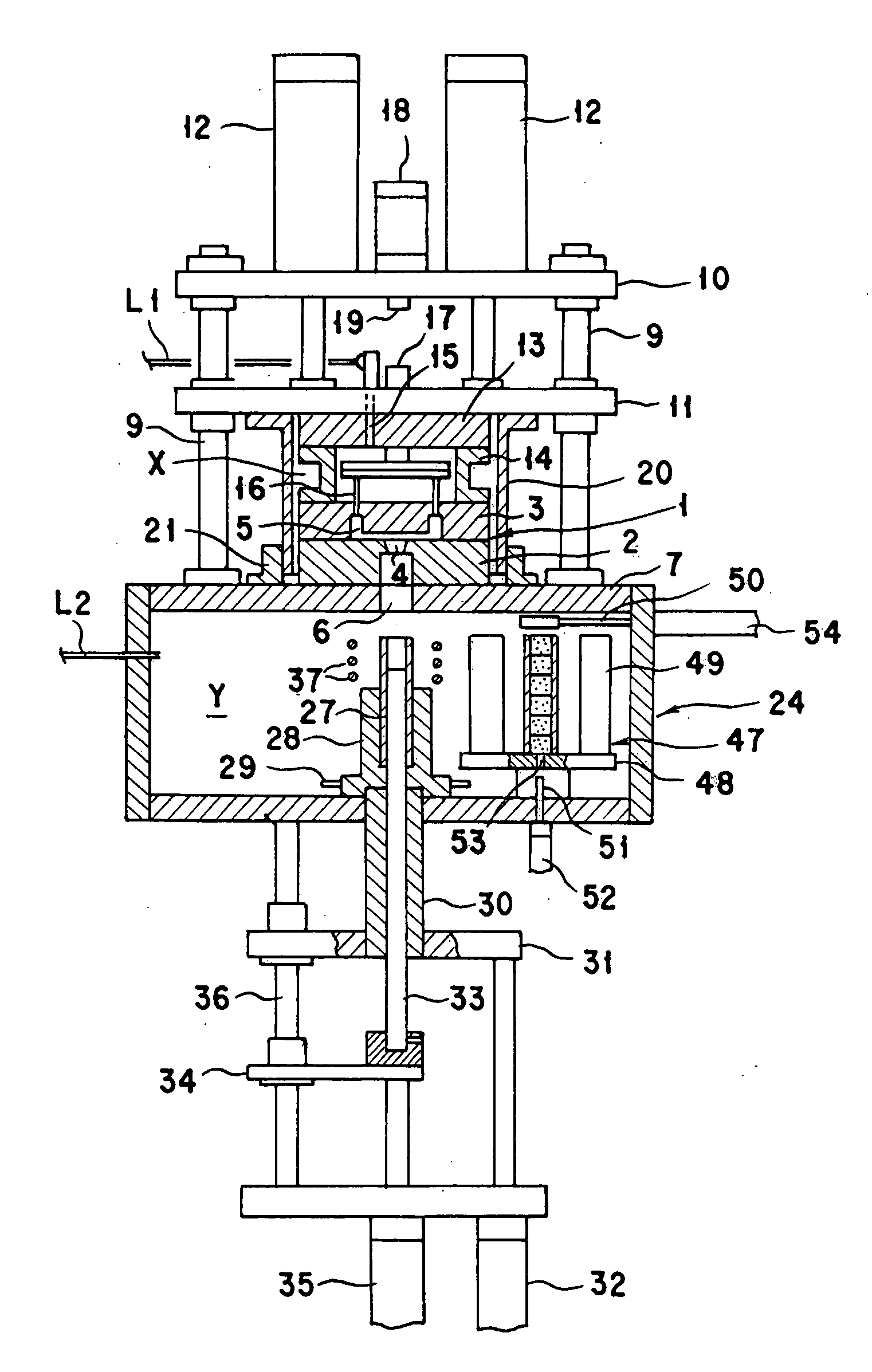
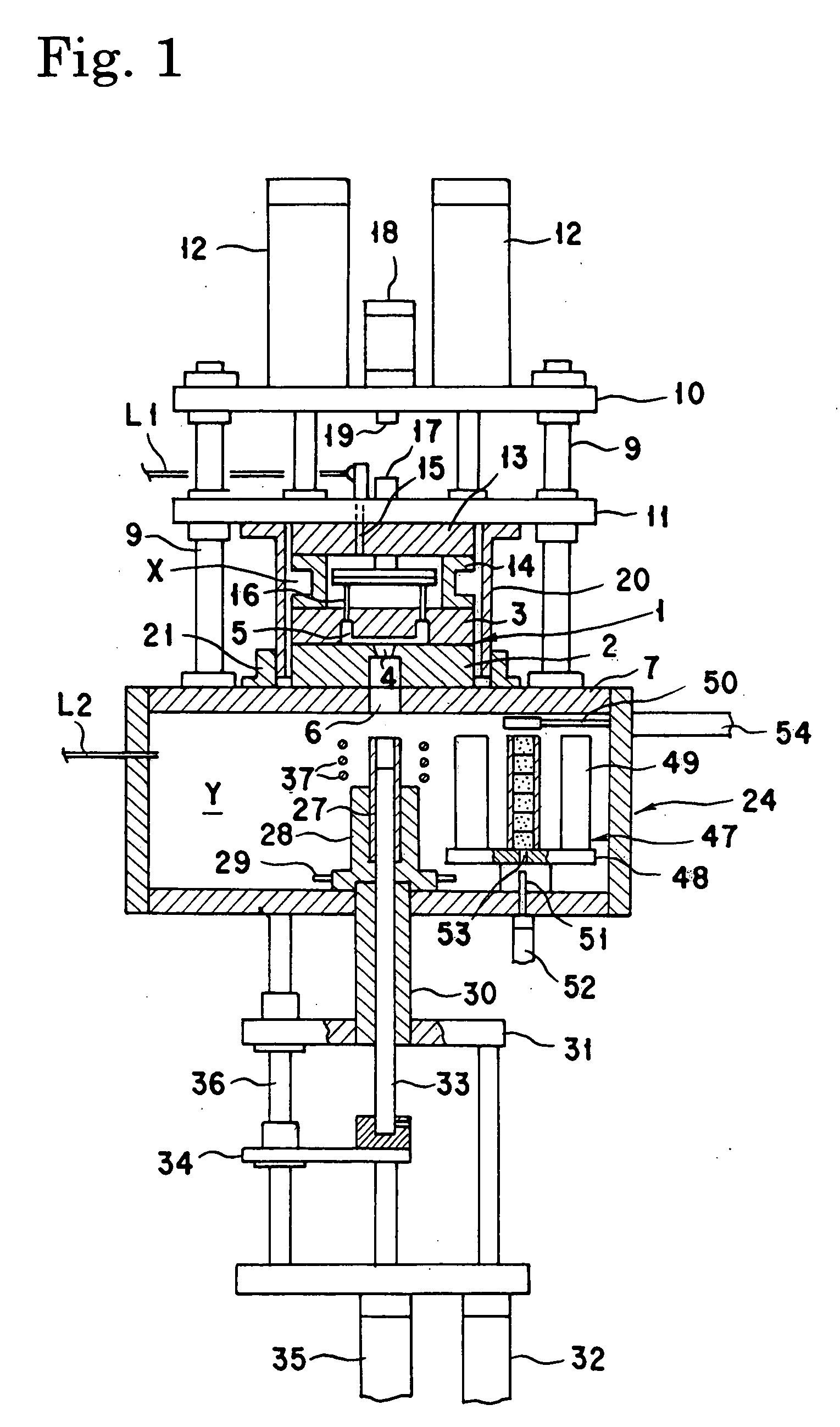
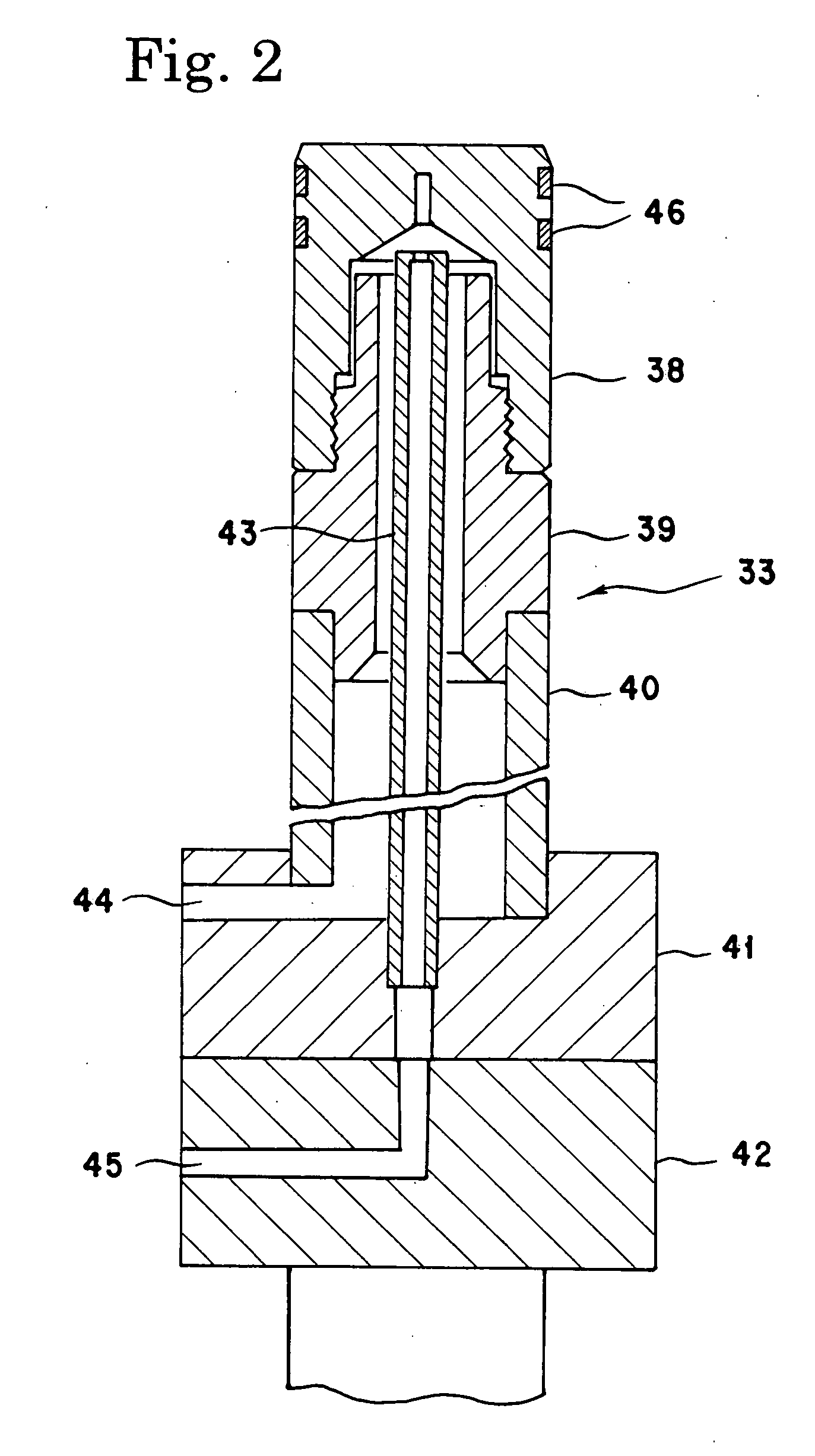
[0031] The characteristic feature of the injection molding apparatus of the present invention resides in that, as described above, in the injection molding apparatus comprising a mold, a sleeve disposed so as to be movable forward and backward toward a pouring gate of the mold, a plunger slidably disposed in the sleeve, and a heating means for heating and melting a raw material lump supplied into a raw material accommodating part formed by an inside wall of the sleeve and the plunger mentioned above, the plunger and / or the sleeve mentioned above is equipped with a cooling means and thus a melt of a metal which has been heated and melted hardly flows into a gap between the plunger and the sleeve. That is, although the molten metal heated to a higher temperature becomes easy to flow into the gap between the plunger and the sleeve, the apparatus is characterized by the fact that it is possible to prevent this phenomenon and make the sliding movement of the plunger in the sleeve becomes...


PUM

PropertyMeasurementUnit
Melting pointaaaaaaaaaa
Flow rateaaaaaaaaaa
Melting pointaaaaaaaaaa

Abstract

An apparatus provided is capable of performing injection molding of a high-melting point metal. The injection molding apparatus comprises a mold, a sleeve disposed so as to be movable forward and backward toward a pouring gate of the mold, a plunger slidably disposed in the sleeve, a heating means for heating and melting a raw material lump supplied into a raw material accommodating part formed by an inside wall of the sleeve and the plunger mentioned above, and a raw material lump supplying means for supplying the raw material lump to the above-mentioned raw material accommodating part from above. For the purpose of ensuring that a melt of a metal which has been heated and melted hardly flows into a gap between the plunger and the sleeve, the above-mentioned plunger and/or sleeve is equipped with a cooling means.

Description

CROSS-REFERENCE TO RELATED APPLICATIONS [0001] This is a continuation of Application PCT / JP2005 / 000377, filed Jan. 14, 2005, which was published under PCT Article 21(2).BACKGROUND OF THE INVENTION [0002] 1. Field of the Invention [0003] This invention relates to an injection molding apparatus, and more particularly to an apparatus which is suitable for the vacuum injection molding of a high-melting point metal, particularly an active metal such as an amorphous alloy, and capable of carrying out the high-speed injection molding of a melt of the active metal while maintaining a clean state thereof. [0004] 2. Description of the Prior Art [0005] Recently, as an injection molding method capable of casting a molded article having no void with an active metal, a molding method which uses a sleeve movable toward a mold and is carried out by supplying a raw material lump into a raw material accommodating part formed by an inside wall of a sleeve and the upper end face of a plunger slidably d...

Claims


Application Information

Patent Timeline
IPC IPC(8): B22D17/12B22D17/20B22D17/30B22D17/28
CPCB22D17/12B22D17/30B22D17/28B22D17/20B22D17/203B22D17/04B22D17/14B22D17/2218
Inventor ISHIDA, MAMORUKAWANISHI, MAKOTO
Owner YKK CORP
Why Eureka
Try Eureka