
Sanitary conveyor

a conveyor and sanitary technology, applied in the field of conveyors, can solve the problems of poor food production efficiency, difficult access to many of the internal components of a typical conveyor, and limited access provided by such openings

Inactive Publication Date: 2006-11-16
AUBRY LARRY +1
View PDF46 Cites 25 Cited by
  • Summary
  • Abstract
  • Description
  • Claims
  • Application Information

AI Technical Summary

Benefits of technology

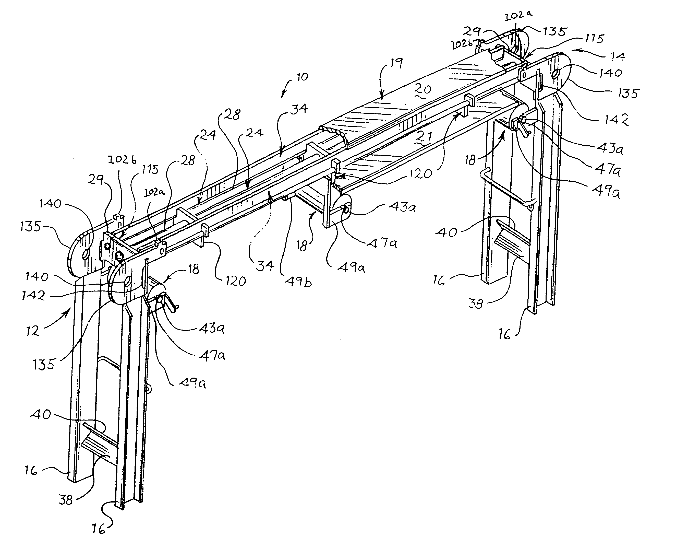
[0012] In one embodiment of the conveyor, the conveyor bed of the frame, supported by the plurality of legs, comprises a plurality of longitudinal rails having at least a sloped upper surface and fixably connected to a plurality of cross members, with the cross members supporting a plurality of wear strips. In another embodiment of the conveyor, the conveyor bed comprises a plurality of longitudinal rails fixably connected to a plurality of end members. The bed further comprises a plurality of intermediate members supporting a plurality of wear strips located substantially between the end members, with the longitudinal rails supporting the intermediate members and having at least a sloped upper surface. The sloped upper surface of the longitudinal rails in both embodiments minimizes the presence of horizontal surfaces and the resultant collection of particulate matter, residues or fluids thereon.
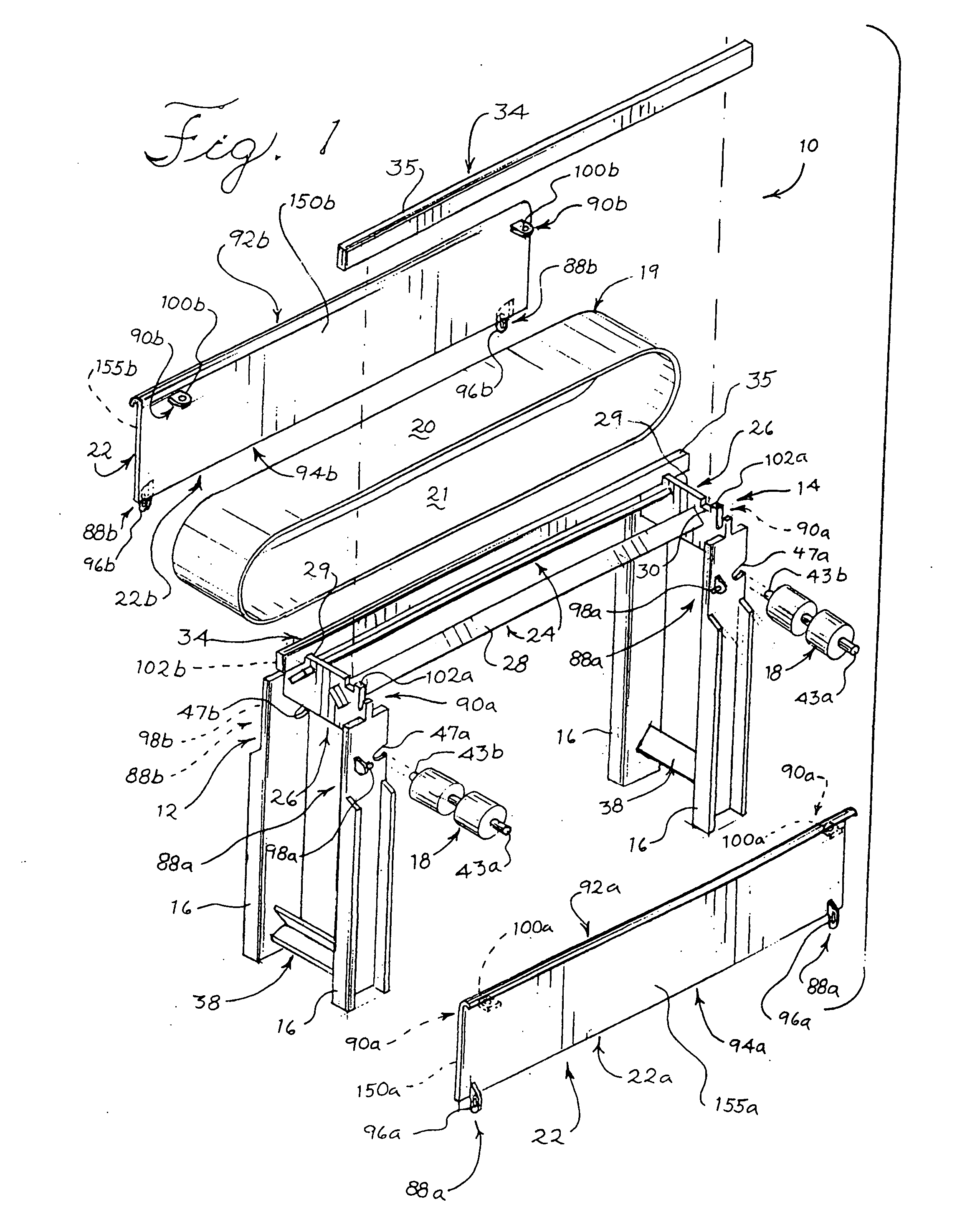
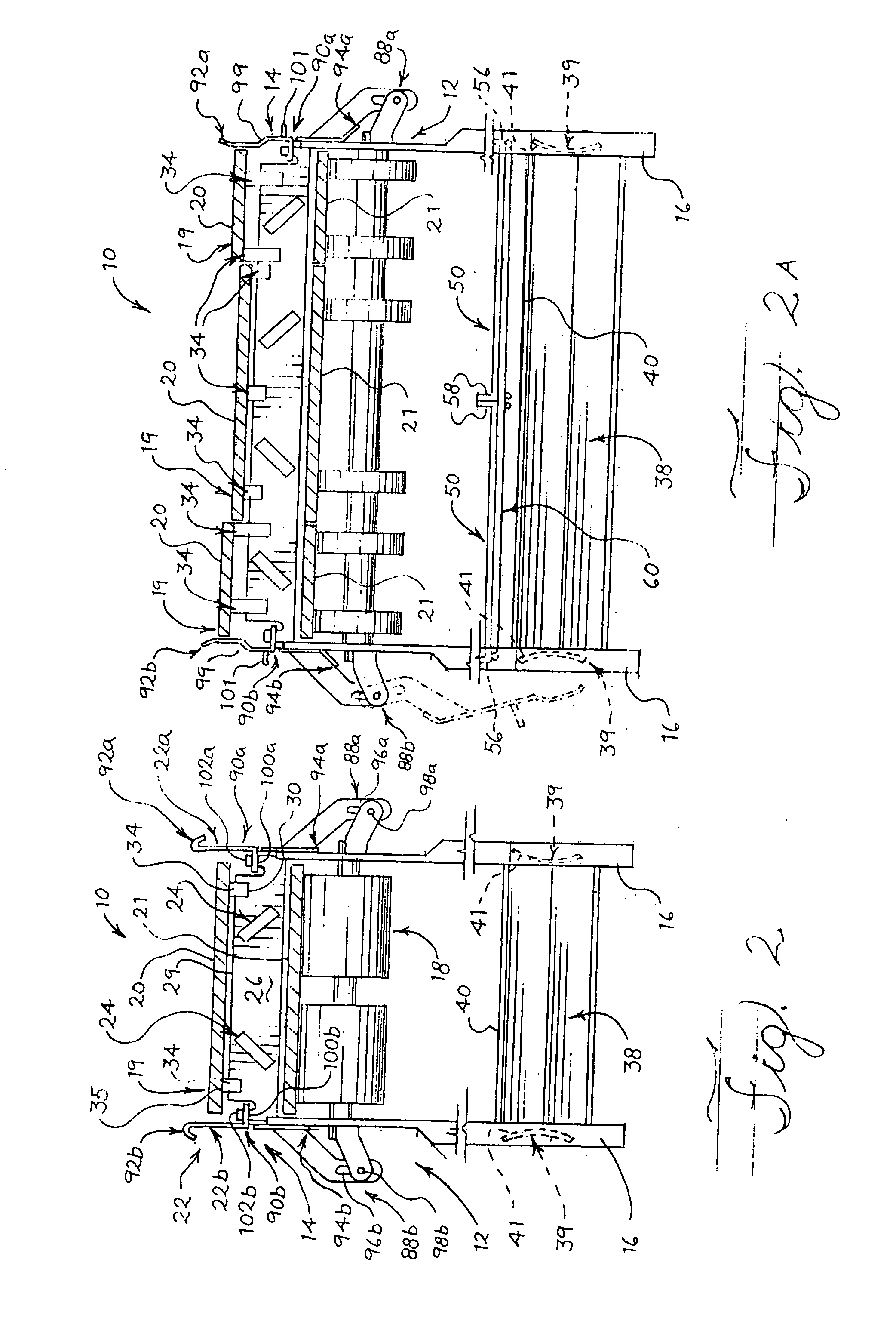
[0024] The traversing movement allows the at least one shield, while in a substantially vertical and closed position, to traverse upwardly and downwardly in relation to the frame in securing the shield to the frame while the rotational movement allows the upper edge of the given shield to rotate outwardly away from the frame about 180 degrees from the substantially vertical and closed position to the fully opened position. When in the fully opened position, the shield is again preferably in a substantially vertical position, but inverted or “upside-down” from the closed position such that the upper edge of the shield is now directed downwardly (i.e. towards the floor) and the inner surface of each shield is directed outwardly. When the at least one shield is in its opened position, it is no longer located laterally of at least the conveyor bed, thus allowing a ready exposure of the bed's components and endless belt to steam, hot water, chemical or pressure-wash cleaning processes. In another embodiment of the invention, the movable attachment of the at least one shield to the frame may also comprise a removable attachment as well to allow for a removal of the at least one shield from the frame during cleaning procedures.

Problems solved by technology

However, because of traditional design, access to many of the internal components of a typical conveyor is difficult, thus requiring a disassembly of the conveyor itself to expose such components to the required cleaning processes.
However, the access provided by such openings is usually limited, thus requiring a disassembly of the side walls and / or belt from the conveyor.
Such disassembly is time consuming and labor intensive, resulting in productivity losses during food production.
Also, the removal of a belt from the conveyor during cleaning procedures presents additional handling issues.
Because conveyor belts are typically very long and cumbersome, their removal from a given conveyor-exposes the belt to potential contaminants i.e., contact with cleaning personnel and / or the floor.
Where such disassembly is not undertaken, perhaps as a time-saving measure, the inaccessible components remain unclean and prone to contamination.
The disassembly of the conveyor's many components during cleaning procedures, such as the side walls, rollers and wears surfaces, may be difficult where these components are assembled with complex fasteners (i.e. nuts and bolts) requiring the use of tools.
The presence of these fasteners during such disassembly thus requires considerable down-time, again resulting in productivity losses during food production.
Furthermore, the presence of complex fasters on the conveyor establishes areas where particulate matter and / or residues from conveyed food products may collect, thus making such areas prone to contamination if not properly cleaned.
Such horizontal surfaces are undesirable because they too establish areas where particulate matter and / or residues can collect, thus creating areas prone to contamination.
The horizontal surfaces are also undesirable because they also promote the collection of cleaning fluids during cleaning processes, thus hindering the desired draining of such fluids from the conveyor.
Such members or components are undesirable because they may harbor contaminants therein if the walls or welds of the respective component are cracked or includes penetrations there-through.
However, filling hollow members or components with an indicating fluid presents obvious disadvantages in a sanitary food production setting where leaked indicating fluids may contaminate the food products themselves.
However, present conveyors utilizing such trays do not include any restraining mechanism that prevents the tray from falling to the floor during cleaning operations, thus making the trays susceptible to contamination.
Also, present conveyors provide no means for positioning the tray in a location that readily allows cleaning personnel to wipe or sweep the tray clean of particulate matter or drips.
Instead, cleaning personnel typically remove the tray from the conveyor and walk it to a waste receptacle to wipe or sweep it free of such matter and / or drips, thus exposing the tray to contamination.
Furthermore, present conveyors do not provide any means for securing the tray in a non-horizontal position during sanitizing operations.
Cleaning personnel instead sanitize the tray while it is located below the belt of the conveyor (in a horizontal position), thus resulting in an undesirable collection of cleaning fluids thereon.

Method used


Image

  • Sanitary conveyor
  • Sanitary conveyor
  • Sanitary conveyor

Examples


Embodiment Construction

[0056] This invention relates generally to conveyors, particularly to a sanitary conveyor adapted for use in production applications requiring usually frequent, periodic cleaning procedures in strict compliance with sanitary standards. Referring initially to FIGS. 1, 2, 8A, 8B and 8C, conveyor 10 in one embodiment comprises a frame 12 comprising a conveyor bed 14 supported by a plurality of legs 16, and at least one rotatable roller 18 supported by the frame. At least one endless belt 19 is in contact with the at least one roller 18 of the conveyor 10, the at least one belt defining both an upper portion (conveying run) 20 and lower portion (return run) 21, with the upper portion (conveying run) 20 supported by the conveyor bed 14. At least one longitudinal shield 22 (not shown in FIG. 8C) is movably attached to the frame 12 and is movable between at least opened and closed positions, the at least one longitudinal shield located laterally of at least the conveyor bed 14 when the shi...


PUM


Abstract

This invention relates generally to conveyors, particularly to a sanitary conveyor adapted for use in production applications requiring usually frequent, periodic cleaning procedures in strict compliance with sanitary standards. The conveyor comprises a frame which comprises a conveyor bed supported by a plurality of legs or a suspension system, and at least one rotatable roller supported by the frame. At least one endless belt is in contact with the at least one roller of the conveyor, the at least one belt defining both an upper portion (conveying run) and lower portion (return run), with the upper portion (conveying run) supported by the conveyor bed. At least one longitudinal shield is movably attached to the frame and is movable between at least opened and closed positions, with the at least one longitudinal shield located laterally of at least the conveyor bed when the shield is in the closed position. At least one catch pan may be removably supported by the frame of the conveyor below the lower portion or return run of the at least one endless belt to catch any wayward particulate matter and / or residual drips that may fall from the lower portion or return run of the belt. At least one shelf may be defined on the at least one movable shield for removably supporting removable conveyor bed components during cleaning operations.

Description

CROSS REFERENCE TO RELATED APPLICATIONS [0001] This application claims priority to U.S. Provisional Patent Application Ser. No. 60 / 680,193 filed on May 11, 2005, and to Ser. No. 60 / 729,867 filed on Oct. 24, 2005.TECHNICAL FIELD OF THE INVENTION [0002] This invention relates generally to conveyors, particularly to sanitary conveyors adapted for use in applications requiring usually frequent, periodic cleaning procedures in strict compliance with sanitary standards. BACKGROUND OF THE INVENTION [0003] Belt-type conveyors are often used in the processing and assembly of food products, pharmaceuticals, electronics and the like. With regard to the processing and assembly of food products, sanitation is a primary consideration and conveyors must be maintained in a clean and hygienic condition to meet government sanitary standards. Food conveyors are typically comprised of multiple components that must be cleaned (i.e. by steam, hot water or chemicals) periodically in compliance with govern...

Claims


Application Information

Patent Timeline
IPC IPC(8): B65G21/08
CPCB65G15/62B65G21/06B65G2207/26B65G2201/027B65G2201/0202
Inventor AUBRY, LARRYZABALA, JOE
Owner AUBRY LARRY
Learn More