Stabilized DC power supply circuit

Inactive Publication Date: 2006-11-16
SHARP KK
View PDF9 Cites 11 Cited by
  • Summary
  • Abstract
  • Description
  • Claims
  • Application Information

AI Technical Summary

Benefits of technology

[0065] It is thus possible to further suppress

Problems solved by technology

Such an increase in current capacity increases a size and costs of the electronic apparatus as a whole.
The circuit disclosed in Patent Literature 1 does not take into account variation in current amplification factor of the output transistor that are caused by variation of the manufacturing process and temperature and, therefore, has an insufficient effect to suppress variation in output peak current.
In the circuit disclosed in Patent Literature 2, on the other hand, variation in resistance value of the current detecting resistor or changes in temperature of this resistance value

Method used


Image

  • Stabilized DC power supply circuit
  • Stabilized DC power supply circuit
  • Stabilized DC power supply circuit

Examples


first embodiment

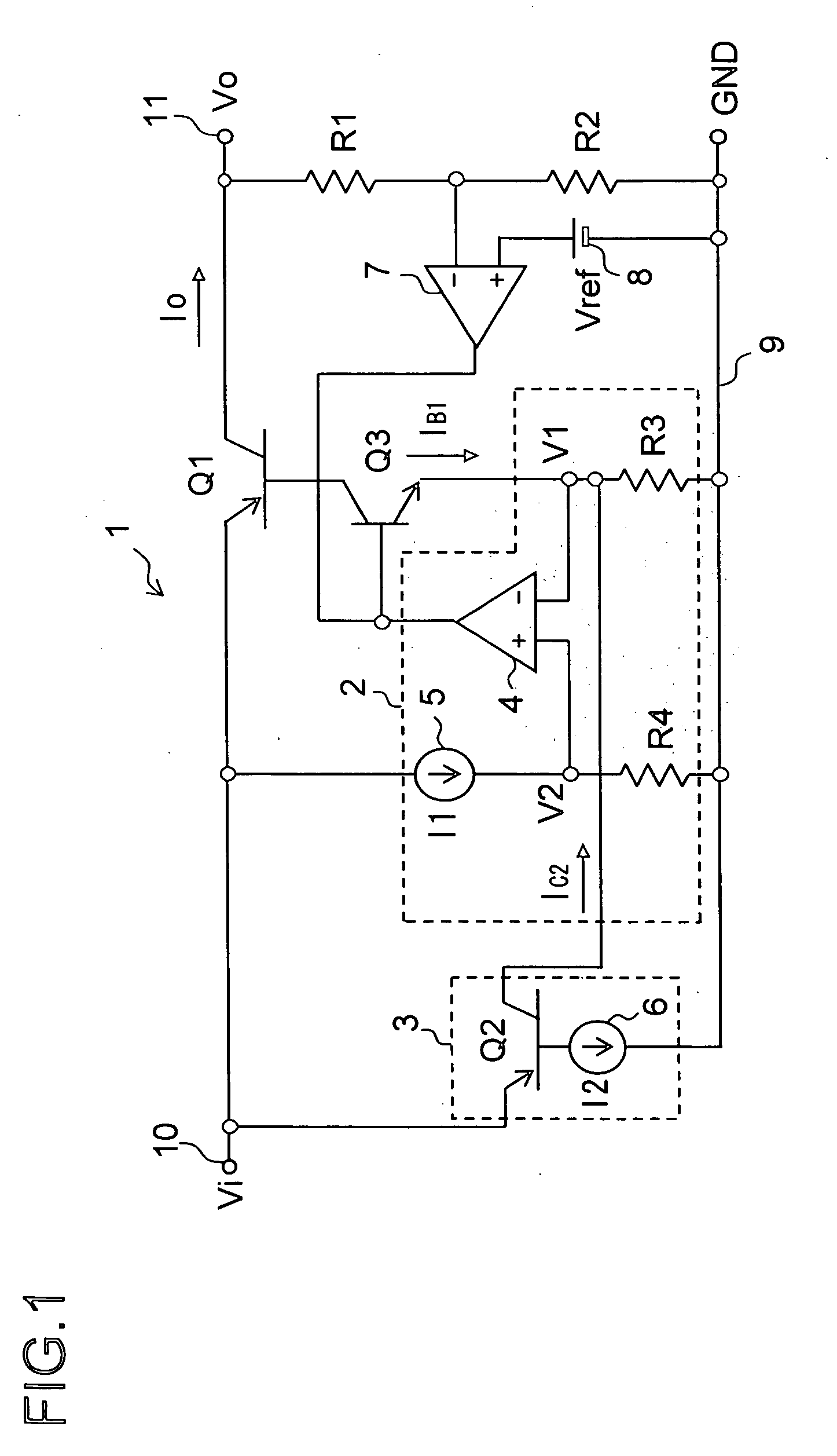
[0100] The following will describe a first embodiment of a stabilized DC (Direct Current) power supply circuit (stabilized DC power supply unit) according to the present invention. FIG. 1 is a circuit diagram of a stabilized DC power supply circuit 1 (hereinafter, referred to as “power supply circuit 1” simply) according to the first embodiment.

[0101] The power supply circuit 1 includes an output transistor Q1 made of a PNP type bipolar transistor, a driving transistor Q3 made of an NPN type bipolar transistor, an output current limiting circuit 2 for limiting a magnitude of an output current lo of the power supply circuit 1, a correction circuit 3 for correcting (suppressing) variation in magnitude of the output current lo limited by the output current limiting circuit 2, voltage division resistors R1 and R2, an error amplifier 7, and a reference voltage source 8.

[0102] The output current limiting circuit 2 includes a differential amplifier 4, resistors R3 and R4, and a constant ...

second embodiment

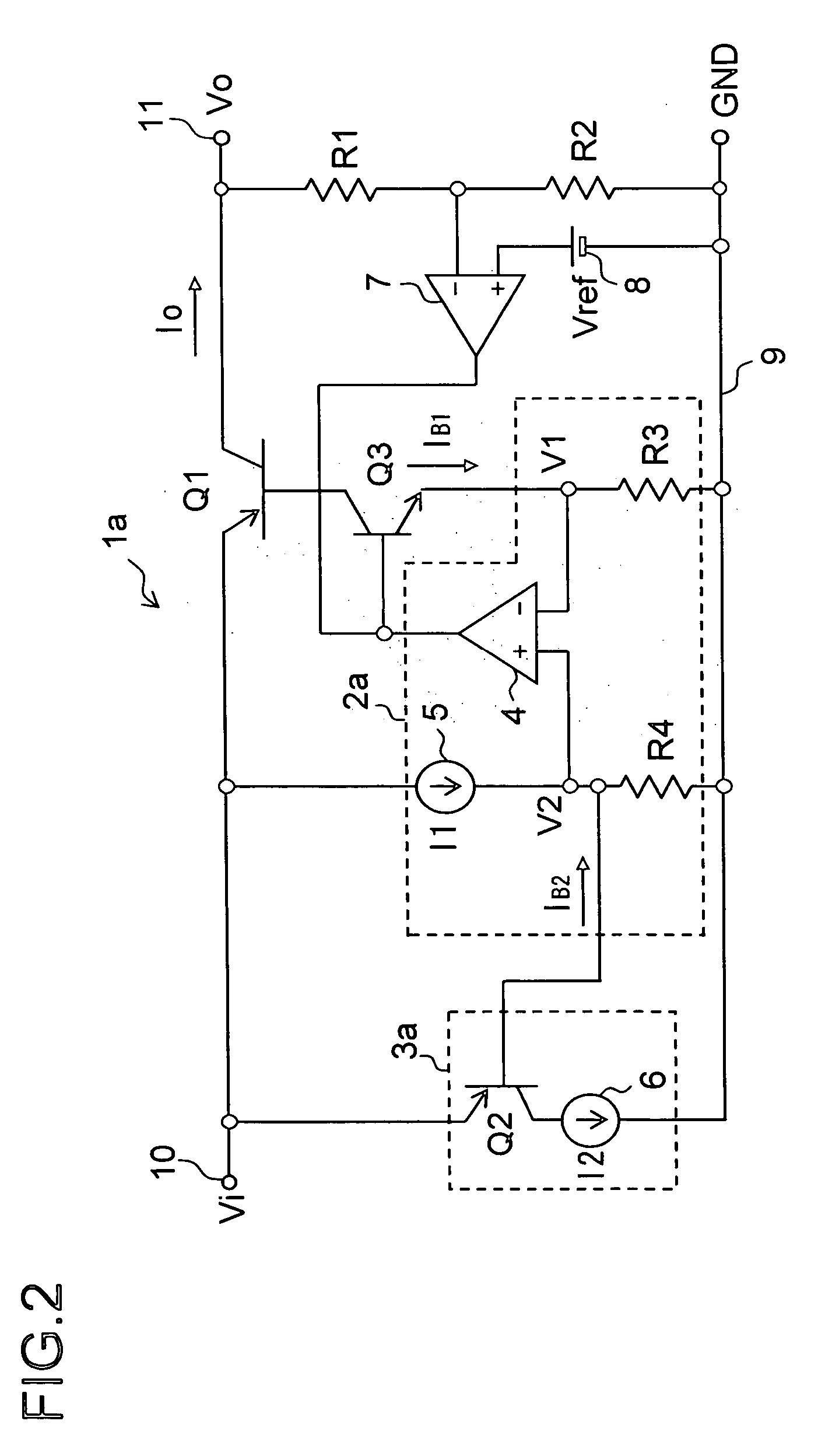
[0130] The following will describe a second embodiment of a stabilized DC power supply circuit (stabilized DC power supply unit) according to the present invention. FIG. 2 is a circuit diagram of a stabilized DC power supply circuit la (hereinafter, referred to as “power supply circuit 1a” simply) according to the second embodiment. In FIG. 2, the same components as those of FIG. 1 are indicated by the same reference numerals, to omit duplicated description of the same components in principle.

[0131] The power supply circuit 1a includes an output transistor Q1, a driving transistor Q3, an output current limiting circuit 2a for limiting a magnitude of an output current Io of the power supply circuit 1a, a correction circuit 3a for correcting (suppressing) variation in magnitude of the output current Io limited by the output current limiting circuit 2a, voltage division resistors R1 and R2, an error amplifier 7, and a reference voltage source 8. That is, the power supply circuit 1a ha...

third embodiment

[0148] First, a stabilized DC power supply circuit (stabilized DC power supply unit) according to the third embodiment is described as follows. FIG. 9 is a circuit diagram of a stabilized DC power supply circuit 1c (hereinafter, referred to as “power supply circuit 1c” simply) according to the third embodiment. In FIG. 9, the same components as those of FIG. 1 etc. are indicated by the same reference numerals, to omit duplicated description of the same components in principle.

[0149] The power supply circuit 1c includes an output transistor Q1, a driving transistor Q3, “an output current limiting circuit 2c constituted of a transistor Q5, and resistors R3 and R4”, “a correction circuit 3c constituted of a correcting transistor Q2, a transistor Q6, and a resistor R5”, a transistor Q4, voltage dividing resistors R1 and R2, an error amplifier 7, and a reference voltage source 8. The transistor Q4 can be thought of as a component of the output current limiting circuit 2c and also as a c...


PUM


Abstract

A stabilized DC power supply circuit of the present invention includes an output current limiting circuit for limiting an output current of an output transistor, and a correction circuit for correcting variation of restriction in the output current caused by variation in a current amplification factor of the output transistor. The correction circuit includes a correcting transistor that is manufactured in the same manufacturing process as the output transistor and formed so as to have the same tendency of manufacturing process variation in current amplification factor etc. as that of the output transistor.

Description

[0001] This nonprovisional application claims priority under 35 U.S.C. §119(a) on Patent Application No. 2005-142136 filed in Japan on May 16, 2005 and Patent Application No. 2006-002119 filed in Japan on Jan. 10, 2006, the entire contents of which are hereby incorporated by reference.BACKGROUND OF THE INVENTION [0002] 1. Field of the Invention [0003] The present invention relates to a stabilized DC (Direct Current) power supply circuit (stabilized DC power supply unit) and, more specifically, a stabilized DC power supply circuit having the function of limiting an output current. [0004] 2. Description of Related Art [0005]FIG. 5 shows a circuit diagram (equivalent circuit diagram) of a conventional example of a stabilized DC power supply circuit. A stabilized DC power supply circuit 101 (hereinafter, referred to as “power supply circuit 101” simply) of FIG. 5 includes an output transistor Q1, a driving transistor Q3, voltage division resistors R1 and R2 for dividing an output voltag...

Claims


Application Information

Patent Timeline
IPC IPC(8): G05F1/00
CPCG05F1/575Y10S323/907G05F1/56
Inventor KANZAKI, TAKAO
Owner SHARP KK
Why Eureka
Try Eureka