Liquid ejection head

Inactive Publication Date: 2006-11-16
SEIKO EPSON CORP
View PDF1 Cites 5 Cited by
  • Summary
  • Abstract
  • Description
  • Claims
  • Application Information

AI Technical Summary

Benefits of technology

[0013] The present invention is proposed by considering the above-described circumstance, and it is an object of the present invention

Problems solved by technology

The increased viscosity of the ink may possibly cause an inconvenience such as an insufficient discharge.
Further, when the control passages are provided in a previously limited area, the necessary length of the control passages is hardly ensured.
Accordingly, a differential thermal expansion exists between these members and a stress is generated in the connecting part owing to the change of temperature or humidity, so that there is a fear that a distortion or separation may possibly arise between the members.
However, in the case of the structure in wh

Method used


Image

  • Liquid ejection head
  • Liquid ejection head
  • Liquid ejection head

Examples


Embodiment Construction

[0032] Now, a best mode for carrying out the present invention will be described below by referring to the accompanying drawings. In below-described embodiments, various kinds of limitations are made as preferable specific examples of the present invention. As long as there is no description that the present invention is especially limited in the following explanation, the scope of the present invention is not limited to these embodiments. Further, in the following description, as a liquid ejection head of the present invention, an ink jet type recording head (refer it simply to as a recording head, hereinafter) mounted on an ink jet recording device will be described as an example.

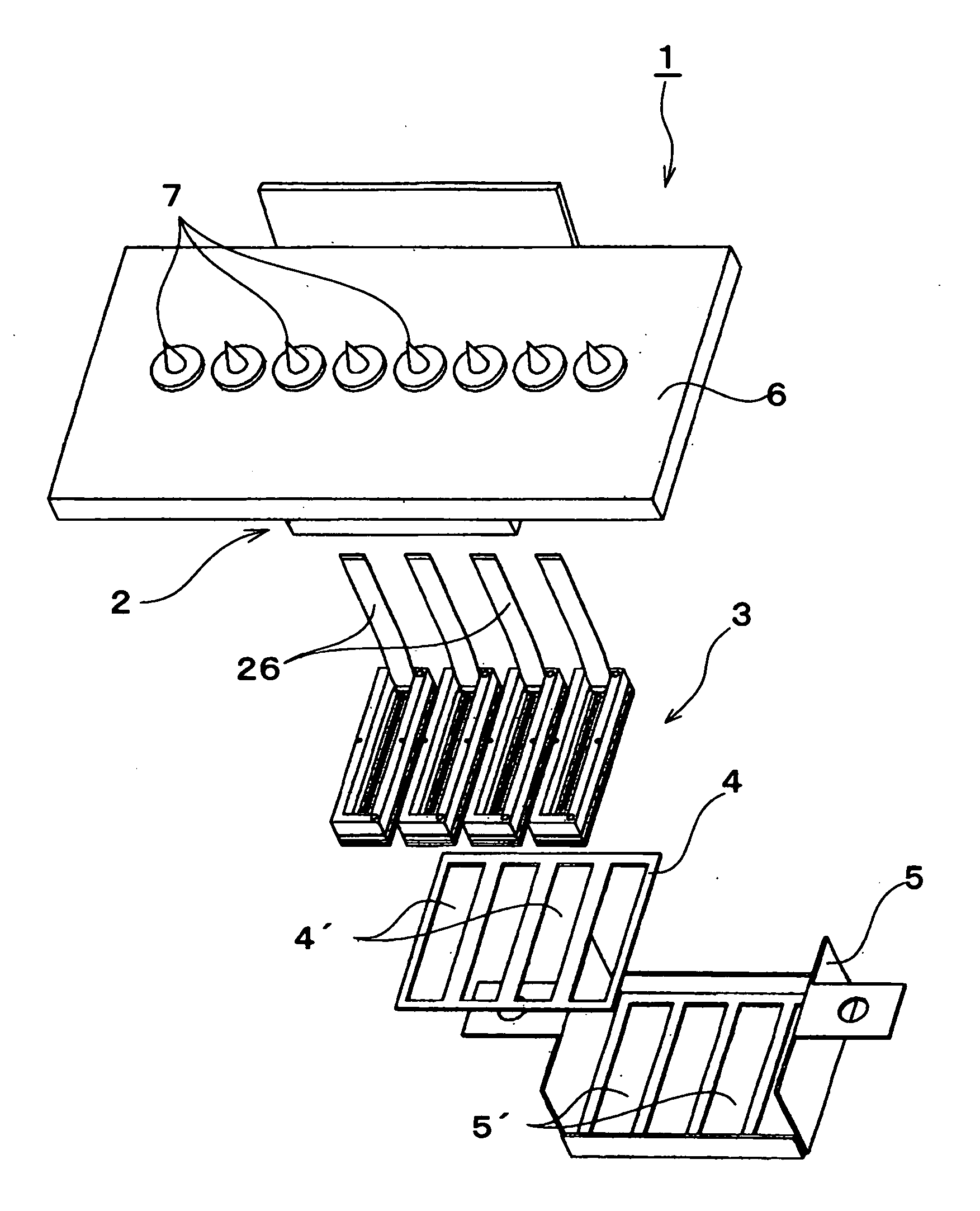
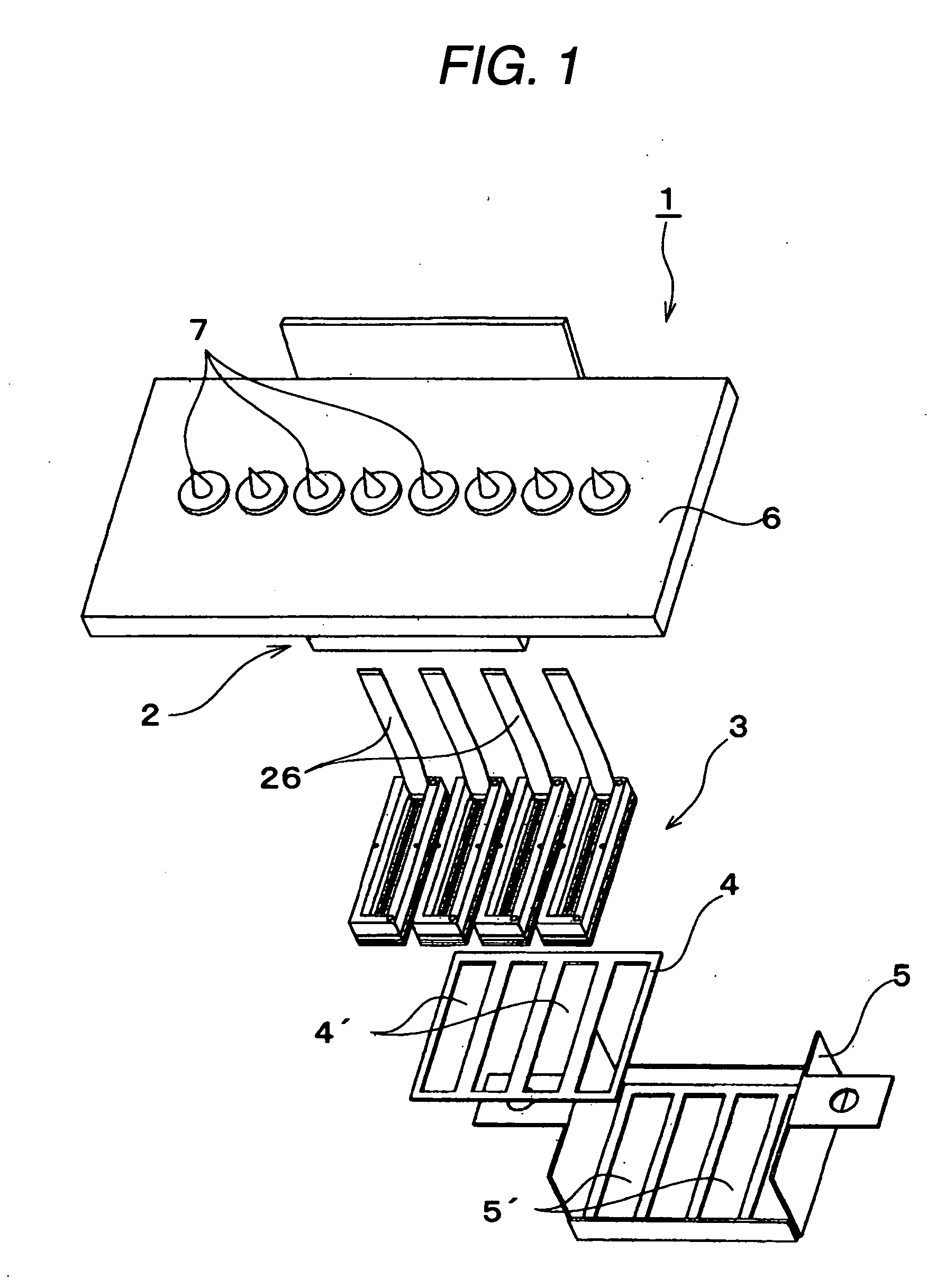
[0033]FIG. 1 is an exploded perspective view showing the structure of a recording head 1 of this embodiment. The recording head 1 in this embodiment is generally composed of a base unit 2, a plurality of head units 3, a head unit fixing plate 4 and a head cover 5.

[0034] The base unit 2 is a box shaped m...


PUM


Abstract

A liquid ejection head including: a head main body including: a cavity unit including a passage forming base plate forming a liquid passage from a common liquid chamber to a nozzle opening via a pressure chamber; and a pressure generating source generating a change of pressure of liquid in the pressure chamber to eject the liquid in the pressure chamber as a liquid droplet from the nozzle opening; and a case member to which the head main body is attached and which includes: a first member provided with a first atmosphere opening passage; and a second member laminated on the first member and provided with a second atmosphere opening passage, wherein the first and second atmosphere opening passages communicate with each other under the laminated state and are opened to atmosphere.

Description

BACKGROUND OF THE INVENTION [0001] 1. Technical Field of the Invention [0002] The present invention relates to a liquid ejection head such as an ink jet type recording head, and more particularly to a liquid ejection head in which the evaporation of liquid in a liquid passage is suppressed and the viscosity of the liquid is prevented from rising. [0003] 2. Description of the Related Art [0004] As a liquid ejection head for generating the variation of pressure in liquid in a pressure chamber to eject the liquid from nozzle openings as droplets, for instance, exemplified are an ink jet type recording head (simply refer it to as a recording head, hereinafter) used for an image recording device such as an ink jet type printer, a color material ejection head used for producing a color filter of a liquid crystal display or the like, an electrode material ejection head used for forming an electrode of an organic EL (Electro Luminescence), an FED (face light emitting display) or the like, a...

Claims


Application Information

Patent Timeline
IPC IPC(8): B41J2/04
CPCB41J2/14233B41J2002/14362B41J2002/14241
Inventor OWAKI, HIROSHIGEGOTO, KAZUTOSHI
Owner SEIKO EPSON CORP
Why Eureka
Try Eureka