Apparatus for supporting a camera

a technology for supporting cameras and tripods, applied in the field of tripods, can solve the problems of difficult use of tripods, inability to know how to operate cameras, and inability to secure the foundations, etc., and achieve the effect of reducing distortion, discomfort and overexposur

Inactive Publication Date: 2006-11-16
FROMM WAYNE G
View PDF11 Cites 34 Cited by
  • Summary
  • Abstract
  • Description
  • Claims
  • Application Information

AI Technical Summary

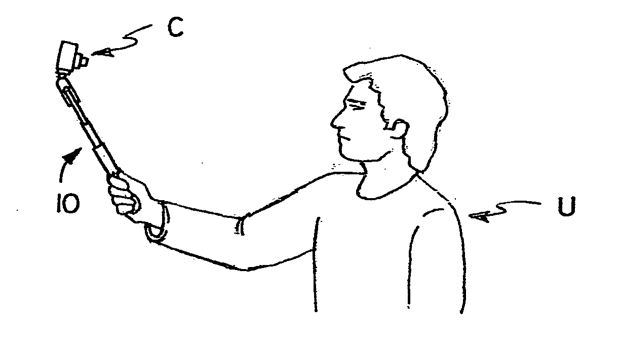
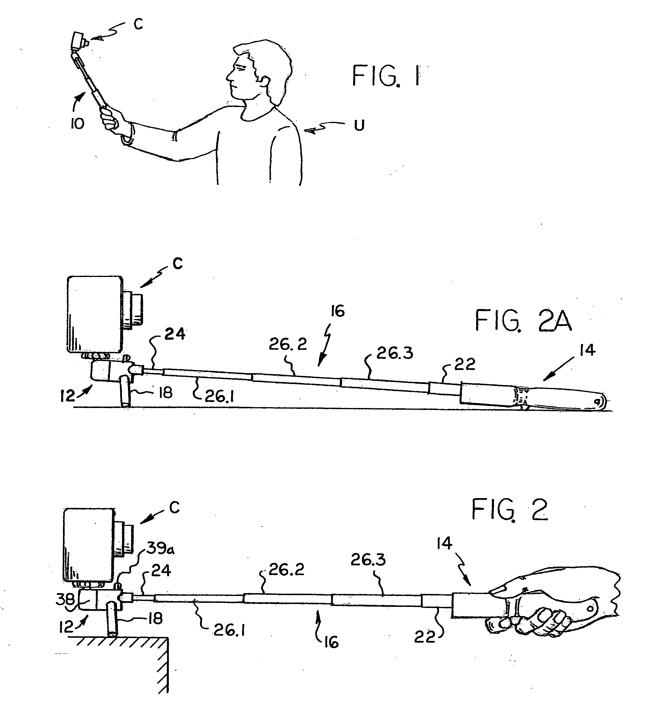
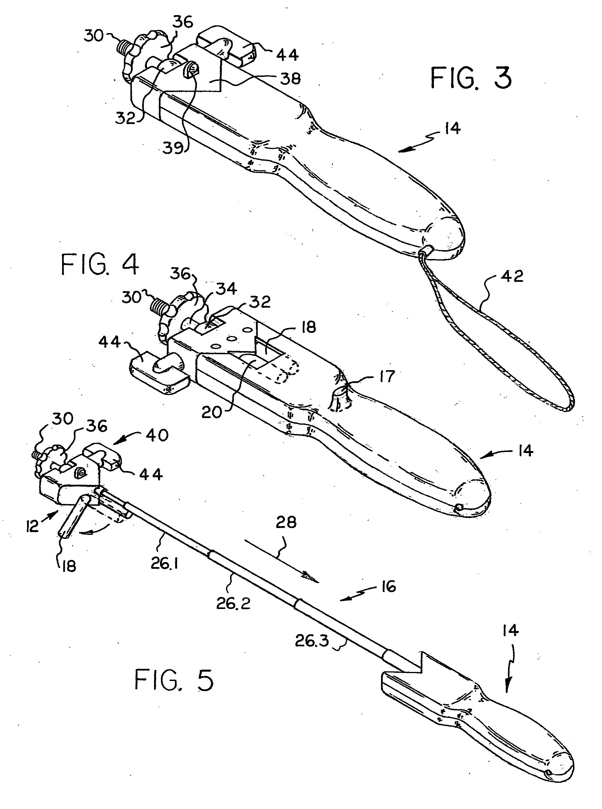
Benefits of technology

[0010] It is an additional object of the present invention to provide an extensible support with a motorized function so that a camera carried by the support can be moved towards and away from the user to, in effect, provide the camera with a zoom function.
[0011] The foregoing objects and other objects and advantages of this invention will be more fully understood after a consideration of the following detailed description taken in conjunction with the accompanying drawings. As can be seen from the following drawings, the apparatus of this invention includes a base assembly which may be secured to a camera, a handgrip, and an elongated support. The base assembly in the illustrated embodiments affixes to the bottom tripod mount on a camera, which camera may be provided with a self-timer, remote shutter release, or a remote control device. The user of the camera and the apparatus of the present invention will hold the handgrip and aim the camera with the lens facing them. This allows self-portra...

Problems solved by technology

While these prior art tripods are suitable for their intended purposed, it is sometimes difficult to use such tripods.
For example, on a beach secure foundations are not readily available.
Strangers can be asked to photograph an individual or group, but they may not know how to operate the camera, or may operate it poorly.
Alternatively, they may run off and steal ...

Method used


Image

  • Apparatus for supporting a camera
  • Apparatus for supporting a camera
  • Apparatus for supporting a camera

Examples


second embodiment

[0038] this invention is illustrated in FIGS. 8-9. In this embodiment there are no tripod legs, and the elongated support 16 may be motorized to cause it to be moved between retracted and extended positions. A camera “C” may be mounted on the base assembly 12. By simply using the rocker switch 29 to operate the motorized extensible and retractable support, the camera can be moved towards and away from the user. This is particularly useful when using camcorders, such as the one illustrated in FIG. 10 at “VC”, to give a zoom effect. Thus, the user “U” of the camera, can point it himself, and by working the rocker switch 29 zoom in and out. If the camera is provided with a swivel LCD the motorized function can also be used cropping the image before it is taken.

[0039] Motorized mechanisms for moving parts towards and away from each other are well known and are therefore not illustrated. One example is the mechanisms used for zoom lenses in cameras. In this embodiment the elongated suppo...

third embodiment

[0041] With further reference to the third embodiment shown in FIG. 10, this embodiment is provided with a D-shaped handgrip. The handgrip is in the shape of a D-shaped handle to provide greater support for the user, which type of handle will offer better support if the camera / camcorder is on the heavy side, and may also prevent horizontal slippage. If the apparatus of FIG. 10 does not have a motorized function, and if the video camera is provided with a remote control device “RC”, the user may use the remote control device to achieve a zoom function. In this regard, it should be noted that is the camera illustrated the swivel LCD view screen may be position so the user can see it.

[0042] While an extensible support has been described which is either motorized or telescoping (similar to that found in compact umbrellas), other forms of extensible supports may be utilized. For example, as shown in FIG. 11, a rack 70 and pinion 72 design may be employed, the pinion being operated by a k...


PUM


Abstract

A camera support assembly including an elongated support, such as a extensible support, which support extends between a base assembly and a handgrip, whereby a user of the camera may secure a camera to the base assembly and, while holding the handgrip, position the camera a distance away, which may be greater than arms length, to capture a still or moving image of the user. The base assembly may be provided with a pair of legs so that the camera support assembly may also be used as a tripod.

Description

CROSS-REFERENCE TO RELATED APPLICATIONS [0001] This application is a continuation-in-part of US application Ser. No. 11 / 125,693, filed May 9, 2005, now abandoned.TECHNICAL FIELD [0002] The present invention relates generally to camera supports and more particularly to an assembly including an elongated support, which is preferably an extensible support, such as a telescoping support, which support extends between a base assembly and a handgrip, whereby a user of the camera may secure a camera to the base assembly and, while holding the handgrip, position the camera a distance away, which may be greater than arms length, to capture a still or moving image of the user. BACKGROUND OF THE INVENTION [0003] Frequently a person with a camera wants to be included in a photograph. The person who is using a camera with a timer function may position the camera on a stationary surface, set the timer to take a picture in a few seconds, and then run to the position where he or she wants to be whe...

Claims


Application Information

Patent Timeline
IPC IPC(8): G03B17/00
CPCG03B17/561F16M13/04F16M11/14F16M11/18F16M11/2092F16M13/022F16M13/00
Inventor FROMM, WAYNE G.
Owner FROMM WAYNE G
Why Eureka
Try Eureka