
Method and system for solder die attach

a technology of solder dies and dies, applied in the direction of mechanical control devices, instruments, process and machine control, etc., can solve the problems of affecting the use of solder, the adjacent die may float away, and the current process equipment cannot attach a single die for each die pad, etc., to facilitate the placement of two or more dies and large die sizes

Inactive Publication Date: 2006-11-16
TEXAS INSTR INC
View PDF44 Cites 4 Cited by
  • Summary
  • Abstract
  • Description
  • Claims
  • Application Information

AI Technical Summary

Benefits of technology

[0004] Some embodiments of the invention provide numerous technical advantages. Other embodiments may realize some, none, or all of these advantages. For example, embodiments of the invention facilitate the placement of two or more die on a leadframe or other substrate. In addition, large die sizes may be utilized because expected fracture areas may be accounted for in the solder die attach process. Another advantage may include monochannel chips that can be placed two times for dual or multichannel applications. No special redesign is necessary.

Problems solved by technology

Current process equipment can only attach a single die for each die pad.
This may cause an adjacent die to float away.
In addition, depending on the size of the die and / or its intended use, cracks may develop in the solder during use because the solder may experience the stress due to the coefficient of thermal expansion (CTE) difference between the die and the leadframe.

Method used


Image

  • Method and system for solder die attach
  • Method and system for solder die attach
  • Method and system for solder die attach

Examples


Embodiment Construction

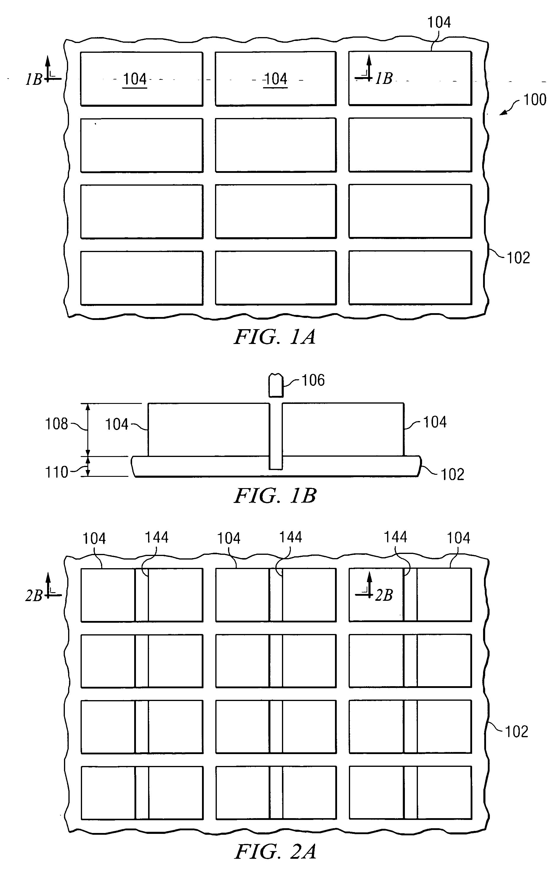
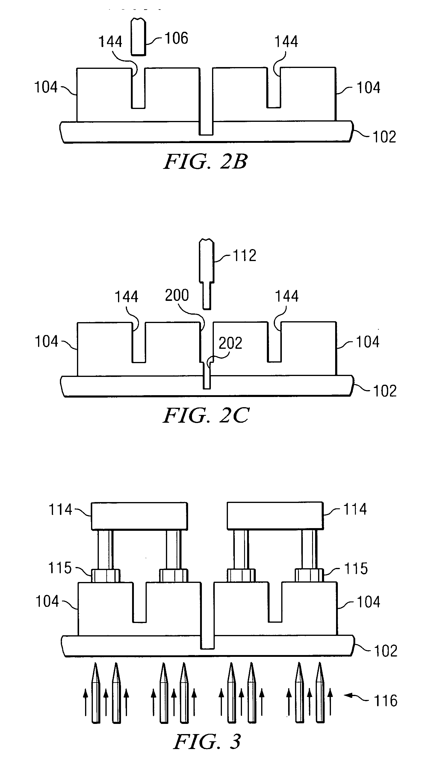
[0013] Example embodiments of the present invention and their advantages are best understood by referring now to FIGS. 1A through 5 of the drawings, in which like numerals refer to like parts.

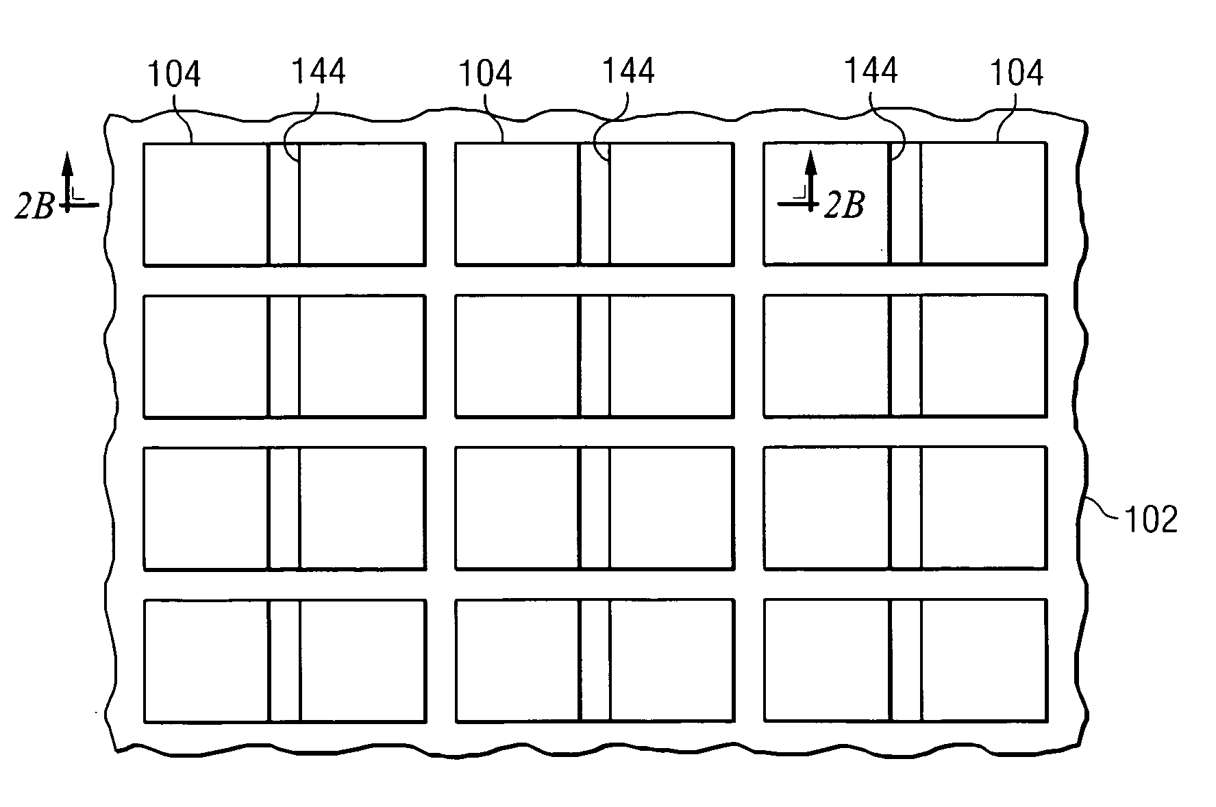
[0014]FIGS. 1A through 5 illustrate systems and methods of solder die attach according to one or more embodiments of the invention. Embodiments of the invention may facilitate the placement of two or more integrated circuit die on a leadframe or other suitable substrate. In addition, large die sizes may be utilized because expected fracture areas may be accounted for in the solder die attach process, as described in further detail below.

[0015]FIGS. 1A and 1B are plan and cross-sectional views, respectively, of a portion of a wafer 100 disposed outwardly from a carrier tape 102 in accordance with an embodiment of the invention. Wafer 100 may be any suitably sized wafer formed from any suitable material, such as silicon or other semiconductor material having a solderable backside (not explicitl...


PUM

PropertyMeasurementUnit
forceaaaaaaaaaa
electricallyaaaaaaaaaa
thicknessaaaaaaaaaa

Abstract

According to one embodiment of the invention, a method of solder die attach includes providing a wafer disposed outwardly from a carrier tape, partitioning the wafer into a plurality of wafer sections, partially partitioning at least some of the wafer sections, picking up a first wafer section of the partially partitioned wafer sections, and placing the first wafer section onto molten solder disposed outwardly from a substrate.

Description

TECHNICAL FIELD OF THE INVENTION [0001] This invention relates generally to the field of integrated circuit packaging and, more specifically, to a method and system for solder die attach for more than one die and reliability improvement for solder die attach for large die. BACKGROUND OF THE INVENTION [0002] Solder is sometimes utilized to attach a die to a die pad on a leadframe or other substrate. Current process equipment can only attach a single die for each die pad. The die is placed in molten solder that is squeezed out from under the die before the placement nozzle is removed. This may cause an adjacent die to float away. In addition, depending on the size of the die and / or its intended use, cracks may develop in the solder during use because the solder may experience the stress due to the coefficient of thermal expansion (CTE) difference between the die and the leadframe. SUMMARY OF THE INVENTION [0003] According to one embodiment of the invention, a method of solder die atta...

Claims


Application Information

Patent Timeline
Patent Type & Authority Applications(United States)
IPC IPC(8): H01L21/00H01L21/67
CPCH01L21/6836H01L2224/05554H01L24/06H01L24/75H01L24/83H01L25/0655H01L2221/68322H01L2221/68327H01L2224/05599H01L2224/48137H01L2224/49171H01L2224/49175H01L2224/83801H01L2224/85399H01L2924/01014H01L2924/01082H01L2924/014H01L2924/14B23D61/025B28D5/022H01L21/6835H01L2924/00014H01L2924/01033H01L21/78H01L2224/45099H01L2924/00H01L2924/00012H01L2924/3512H01L2924/181
Inventor LANGE, BERNHARD
Owner TEXAS INSTR INC
Learn More