Flow metering system

a flow metering and flow tube technology, applied in the direction of volume/mass flow measurement, measurement devices, instruments, etc., can solve the problems of not realizing the further advantage, process will not provide accurate flow rate, and the flow tube cross-sectional area of bornhop and yin et al. cannot accommodate the variation in the cross-sectional area of the flow tube, etc., to achieve accurate measurement of volumetric flow

Inactive Publication Date: 2006-11-23
SAGE BURTON H +2
View PDF4 Cites 49 Cited by
  • Summary
  • Abstract
  • Description
  • Claims
  • Application Information

AI Technical Summary

Benefits of technology

[0006] An apparatus and method for accurately measuring volumetric flow of a liquid along a conduit is described. Bornhop in U.S. Pat. No. 6,381,025 and Yin, et al in U.S. Pat. No. 6,386,050 describe an interferometric method of measuring index of refraction changes in a liquid flowing along a conduit and the use of this method to measure the index of refraction of the liquid and the velocity of the liquid flowing along the conduit. These devices and methods have the distinct advantage that the flow of the fluid may be monitored without contact with either the fluid or the conduit within which the fluid is flowing. This invention expands the teachings of Bornhop and Yin et al in several important ways. First, it teaches that interference is not necessary in order to measure the refractive index or the liquid velocity as described. Thus, a light source with sufficient coherence to establish an interference patterns is not required. Although a laser may be used, virtually any light source with sufficient intensity to activate the detectors may be used.

Problems solved by technology

Second, while Bornhop and Yin et al realize the value of their non-contact interferometric methods in maintaining a contamination free conduit and in eliminating the thermal effects of contact based thermal time of flight systems, they have not realized the further advantage of being able to use a removable and disposable conduit that mates with the heat source and interferometric flow sensor.
Third, the methods of Bornhop and Yin et al do not accommodate variations in the cross-sectional area of the flow tube.
In a system with a disposable conduit, this process will not provide an accurate flow rate.
Further, in a fluid delivery system where the conduit is not disposable and is used over a wide temperature range, thermal expansion will cause the dimensions of the conduit to change.
Hence any calibration that may have been done with an earlier conduit will not be appropriate for the new conduit.
And a calibration performed at one temperature will not be appropriate for other temperatures.

Method used


Image

  • Flow metering system
  • Flow metering system
  • Flow metering system

Examples


Embodiment Construction

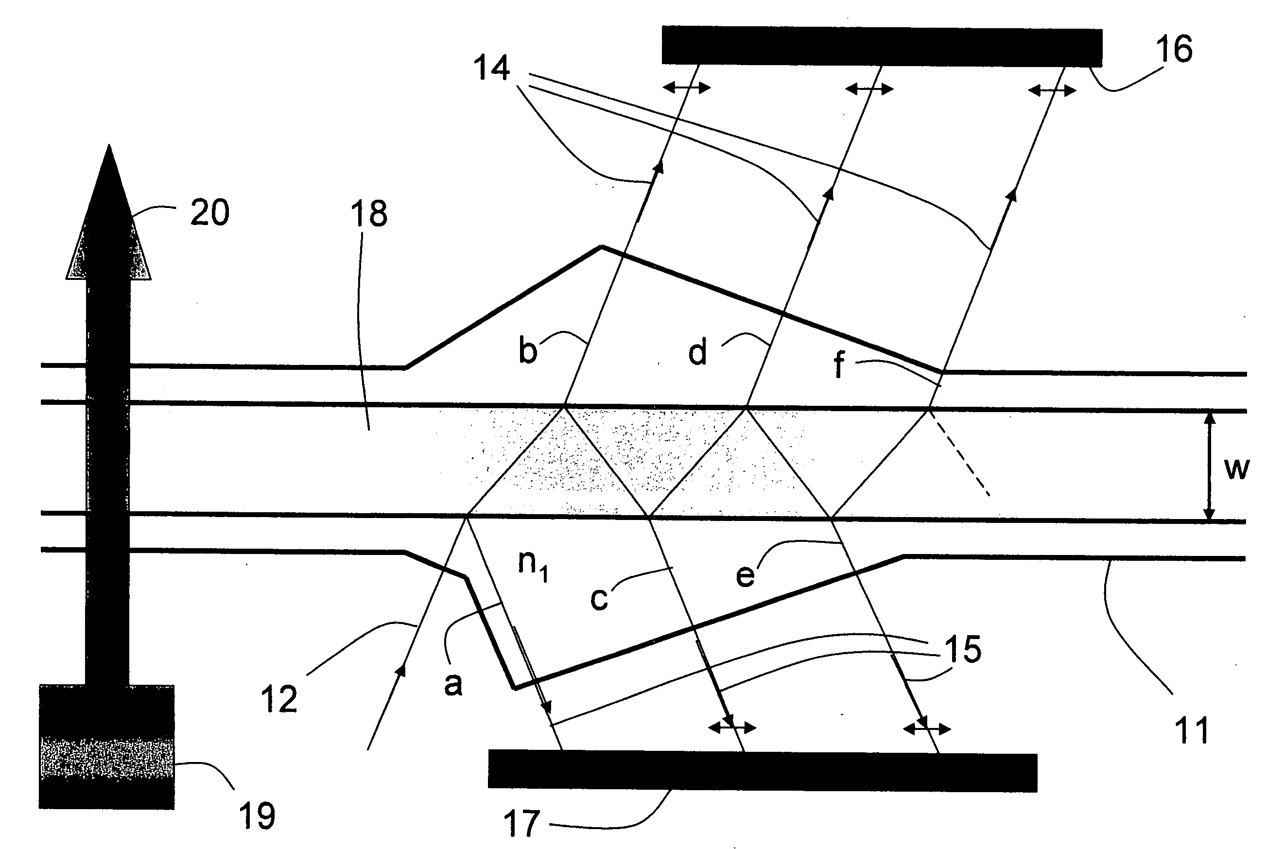
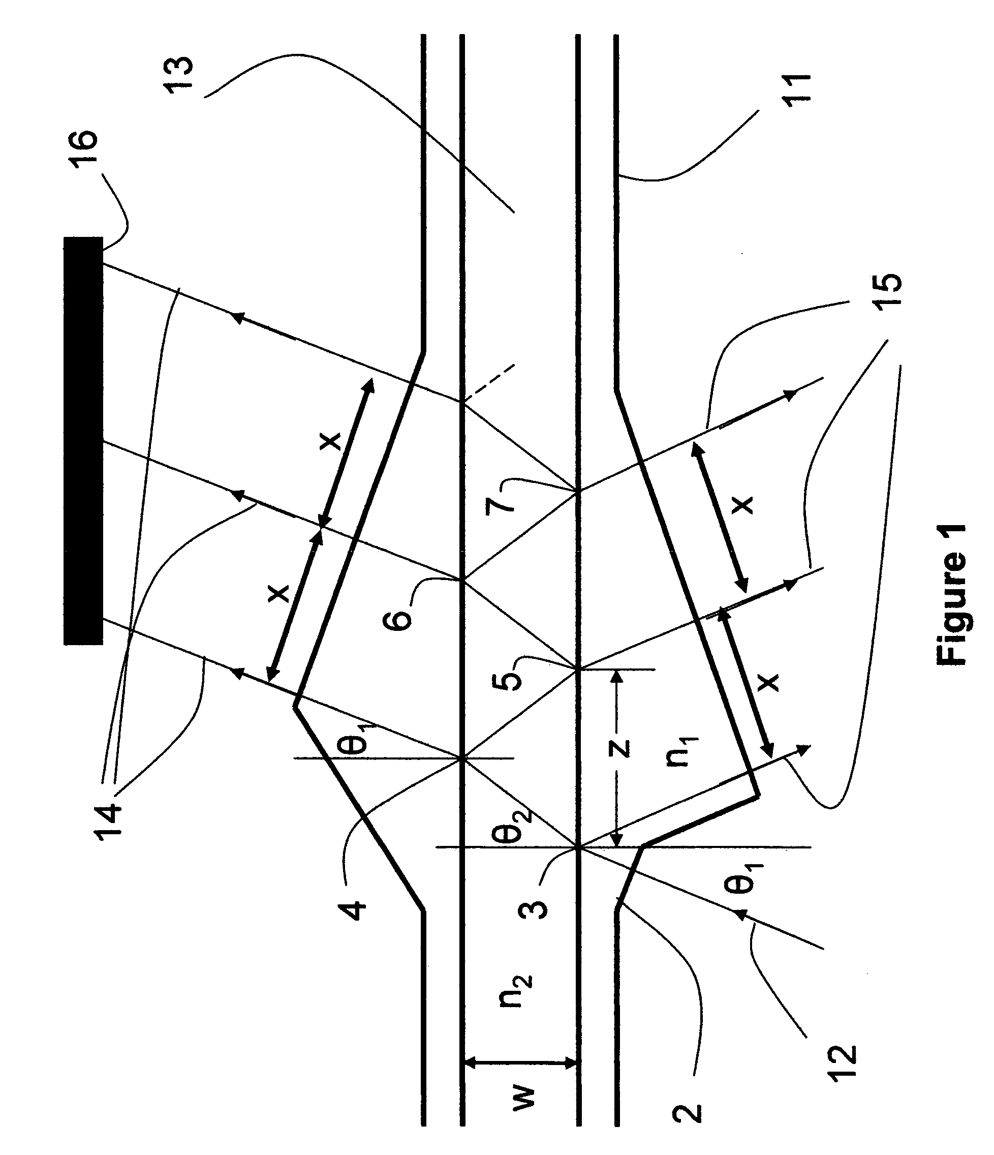
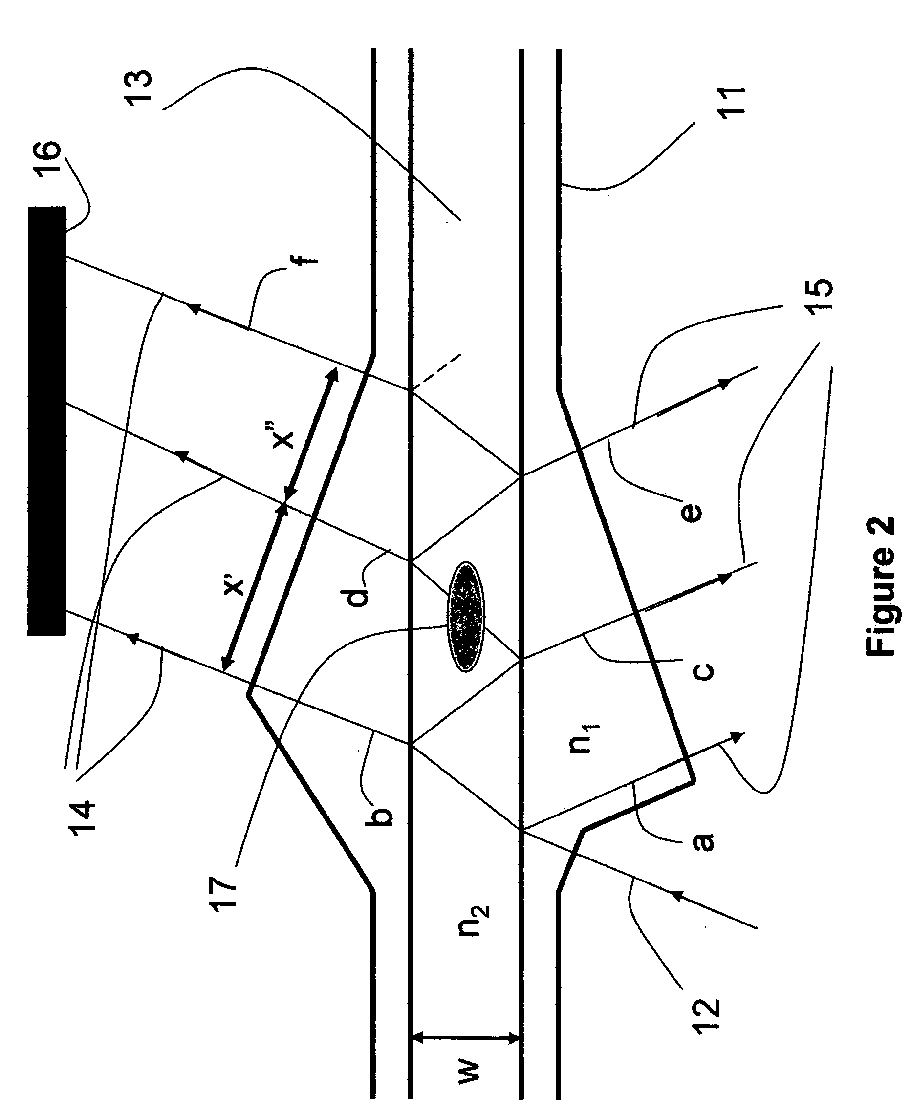
[0021]FIG. 1 shows the pattern of light resulting from a single incident beam 12 on a capillary in a first embodiment of the invention. Incident beam 12 may be generated by a laser, or by an LED, or a tungsten lamp, or any other source of light sufficiently strong to provide the needed signals from detector 16. Incident beam 12 enters conduit 11 through side wall 2. One angle of incidence that avoids unwanted reflection at side wall 2 is normal incidence as shown. Incident beam 12 continues unrefracted into and through the wall of conduit 11 until it enters the fluid stream at position 3. At position 3 a portion of light beam 12 is refracted and a portion is reflected when fluid 13 has a refractive index other than the refractive index (n1) of the conduit 11. The reflected portion of incident beam 12 leaves the conduit as one of reflected beams 15. The refracted portion of incident beam 12 continues through fluid 13 until it reaches the opposite side of conduit 11 at position 4 wher...


PUM


Abstract

A non-contact fluid flow monitor that enables a two component system comprised of a removable conduit and reusable flow rate sensor is described. The monitor is capable of measuring fluid flow velocity and the dimensions of the removable conduit thereby calculating a true volumetric flow rate. The monitor is further capable of determining the refractive index of the fluid thereby verifying that the fluid flowing through the conduit has this expected property.

Description

FIELD OF THE INVENTION [0001] This invention relates to devices and methods for measuring fluid flow. More specifically, the invention relates to fluid delivery systems that introduce a thermal tracer into the fluid and monitor the progress of the thermal tracer by optically detecting the change of index of refraction inherent in the thermal tracer. BACKGROUND. [0002] Devices and methods for measuring the flow of a fluid in a conduit using the thermal “time of flight” method are known. Such flow sensors are useful in measuring fluid flow in analytical systems such as high performance liquid chromatography (HPLC) systems, in drug delivery systems, and other systems such as fluid mixing systems where accurate knowledge of the quantity of fluid being delivered to a delivery site is needed. Jerman et al in U.S. Pat. No. 5,533,412 teach an integrated thermal time of flight device on a substrate where elements to introduce a thermal tracer into the flowing stream using thermal elements ar...

Claims


Application Information

Patent Timeline
Patent Type & Authority Applications(United States)
IPC IPC(8): G01F1/708G01F1/7084G01F1/7086
CPCG01F1/7086G01F1/7084
Inventor SAGE, BURTON H.KLIMOWILZ, MICHAEL A.SIMMONS, MEGHAN BURNS
Owner SAGE BURTON H
Why Eureka
Try Eureka