
Cooking device with a cooking chamber outlet

a technology of cooking device and cooking chamber, which is applied in the field of cooking device with cooking chamber, can solve the problems of compromising the main purpose of the entire cooking device, the entire cooking device cannot be used, and the cleaning is already impossible, and achieves the effect of substantial technical reliability

Active Publication Date: 2006-11-23
MKN MASCHFAB KURT NEUBAUER
View PDF14 Cites 16 Cited by
  • Summary
  • Abstract
  • Description
  • Claims
  • Application Information

AI Technical Summary

Benefits of technology

[0015] An air trap has a water reservoir, which prevents odors or vapors from being able to pass through the assembly.
[0033] Finally it is preferred if a separating element is arranged in the air trap, which separates a region of the air trap, in which coarse particles are deposited, from an extraction region of the air trap for the transport means. This prevents coarse contaminating particles such as crumbs from being entrained with the conveyed fluid into the cooking chamber again. Instead, they lie ready to be easily conveyed to the waste water connection.

Problems solved by technology

While this automatic cleaning is indeed quite effective, certain aspects still cause problems therein.
For example, if the locking device provided for this should not function as a result of a malfunction or if it is also only partially impaired, then this also compromises the main purpose of the entire cooking device, since the contaminated liquid can no longer exit from the cooking chamber, for example.
Then, the entire cooking device can no longer be used, although only an ancillary unit with a subsidiary purpose is affected.
However, at least cleaning is already rendered impossible as a result.
Moreover, the cross-sections of the relevant pipe sections for a closure are relatively large for technical reasons.
As a result of this, the appropriate devices for closing these pipes are also quite expensive.

Method used


Image

  • Cooking device with a cooking chamber outlet
  • Cooking device with a cooking chamber outlet
  • Cooking device with a cooking chamber outlet

Examples


Embodiment Construction

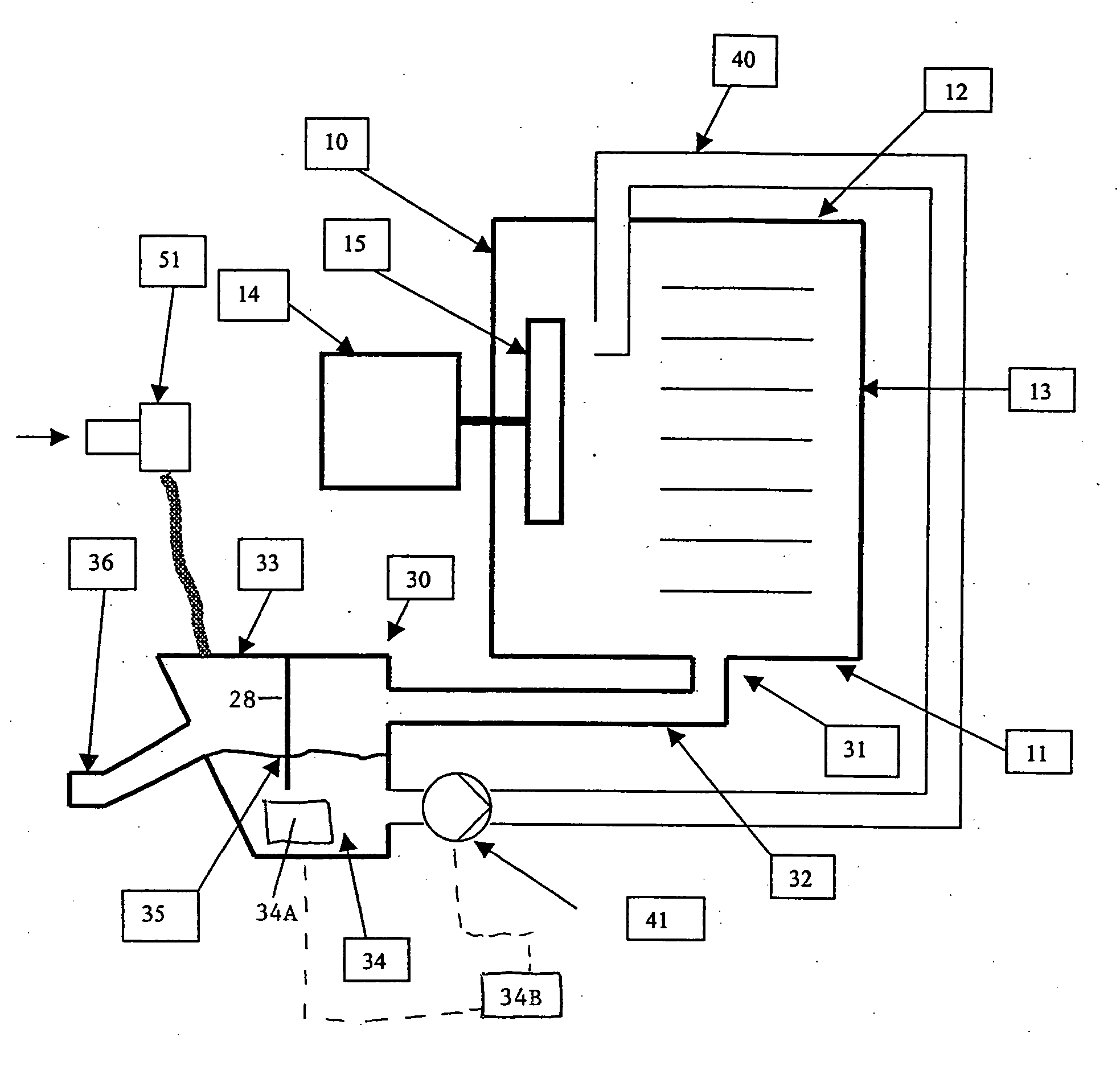
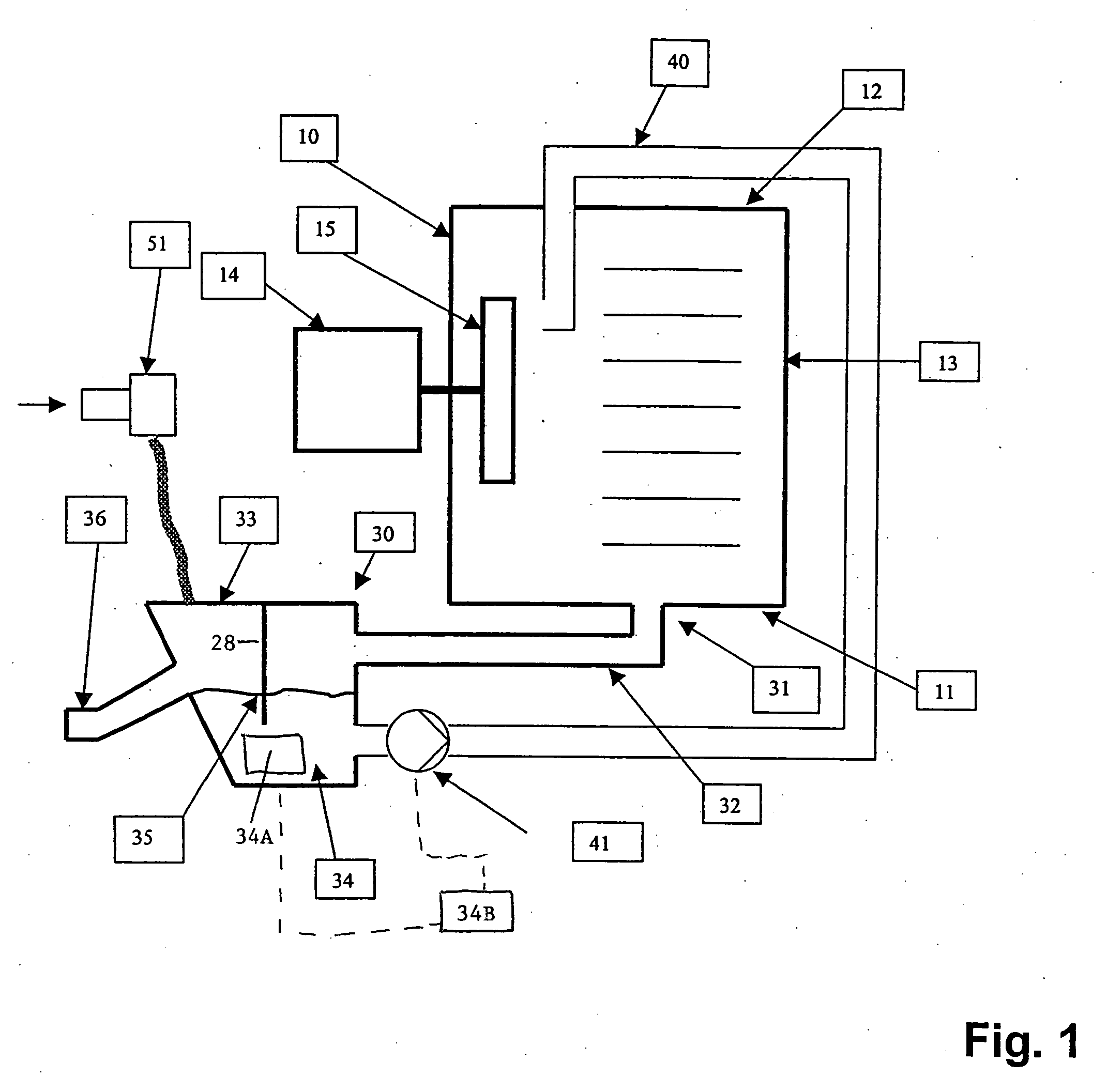
[0041] A first embodiment of a complete assembly according to the invention is shown schematically in FIG. 1. This shows a cooking device with a cooking chamber 10. The cooking chamber 10 has a base 11, an upper side 12 and a side wall 13. The details have been omitted here.

[0042] In this embodiment, a circulation system 14 for the cooking chamber 10 is located on one side wall 13 of the cooking chamber 10. The circulation system 14 has a motor and a fan wheel 15 located inside the cooking chamber 10.

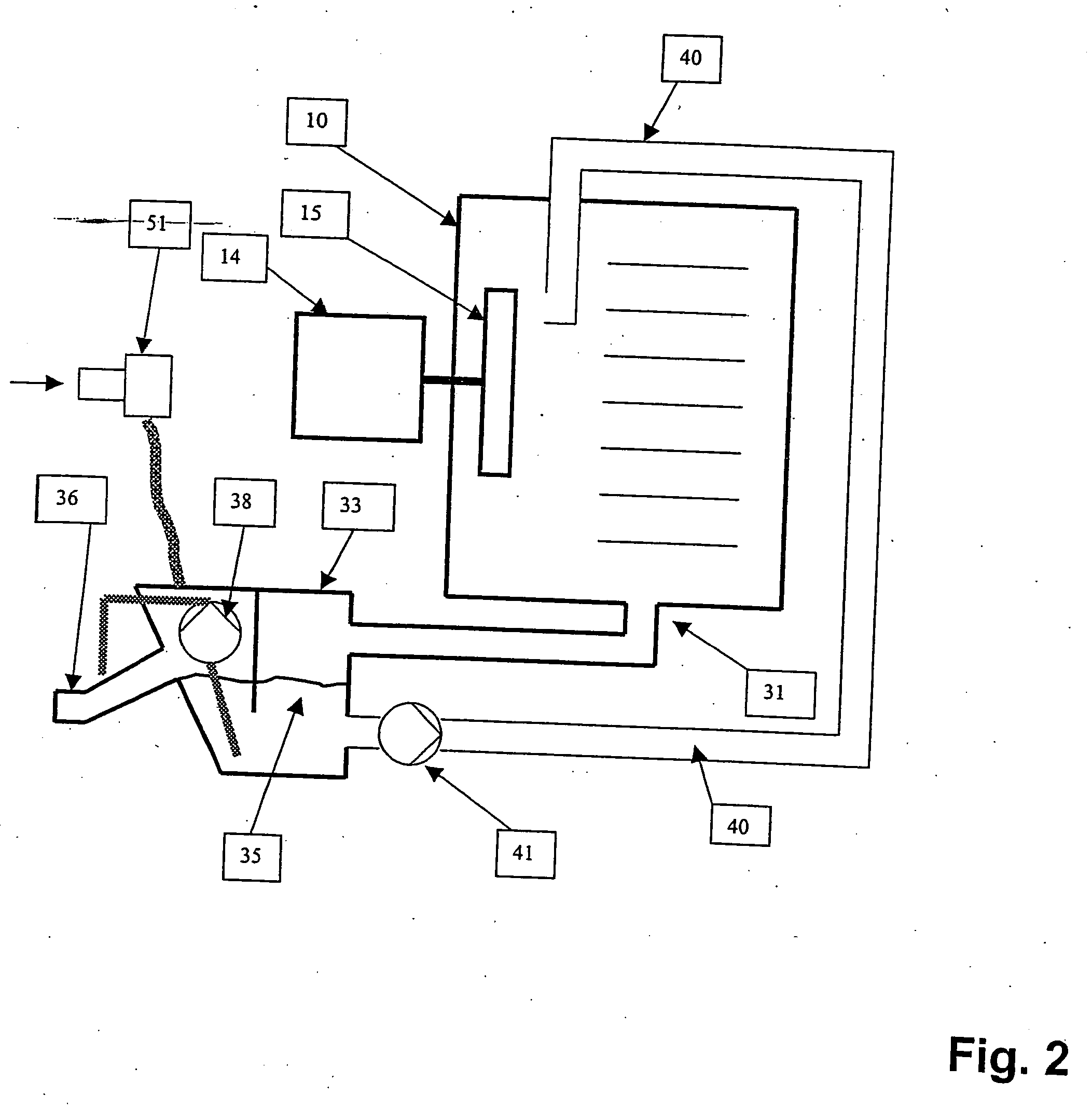
[0043]FIG. 1 also shows a waste water assembly, i.e. an outflow system 30 for a fluid, which has formed in the cooking chamber 10. This outflow system 30 begins with a cooking chamber outlet 31 in the base 11 of the cooking chamber 10. A pipe 32 leads out of the cooking chamber outlet 31 on to an air trap 33.

[0044] A water reservoir 34 is located in the air trap. The surface or water level of this water reservoir 34 in the air trap 33 is also referred to as the water line 35.

[0045] ...


PUM


Abstract

A cooking device has a cooking chamber as well as a cooking chamber outlet for a fluid. An air trap is provided downstream of the cooking chamber outlet. A device outlet is arranged in turn downstream of the air trap. A water reservoir is located in the air trap. A connection pipe leads from the water reservoir in the air trap into the cooking chamber. Associated with the connection pipe is a transport means, which permits a controllable supply of fluid from the water reservoir in the air trap into the cooking chamber.

Description

FIELD OF THE INVENTION [0001] The present invention relates in general to a cooking device with a cooking chamber and pertains more particularly to a cooking device having a cooking chamber with an outlet for a fluid for cleaning purposes. BACKGROUND OF THE INVENTION [0002] Cooking devices are used for the preparation of foods. The foods located therein are heated. During this process, vapors or steam or also other fluids are formed, which must be removed. For this reason, a cooking chamber outlet, through which these fluids then pass to a cooking device outlet or waste water connection and are disposed of, is generally located in the base of the cooking chamber of the cooking device. [0003] Such a cooking device with a cooking chamber outlet for a fluid, a device outlet, a water reservoir, a connection pipe from the water reservoir into the cooking chamber, a transport means associated with the connection pipe for the controllable supply of fluid from the water reservoir into the c...

Claims


Application Information

Patent Timeline
IPC IPC(8): A23B4/044
CPCF24C14/005
Inventor HELM, PETER
Owner MKN MASCHFAB KURT NEUBAUER
Learn More