[0006] The present invention was conceived in view of the problem described above and it is a principal object of the present invention to provide a clamping plate that makes it possible to store a plurality of clamping plates in a component storage box or the like without the clamping plates becoming jammed together.
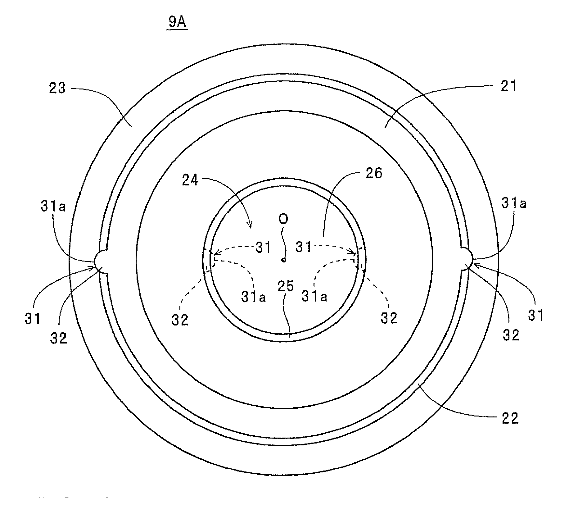
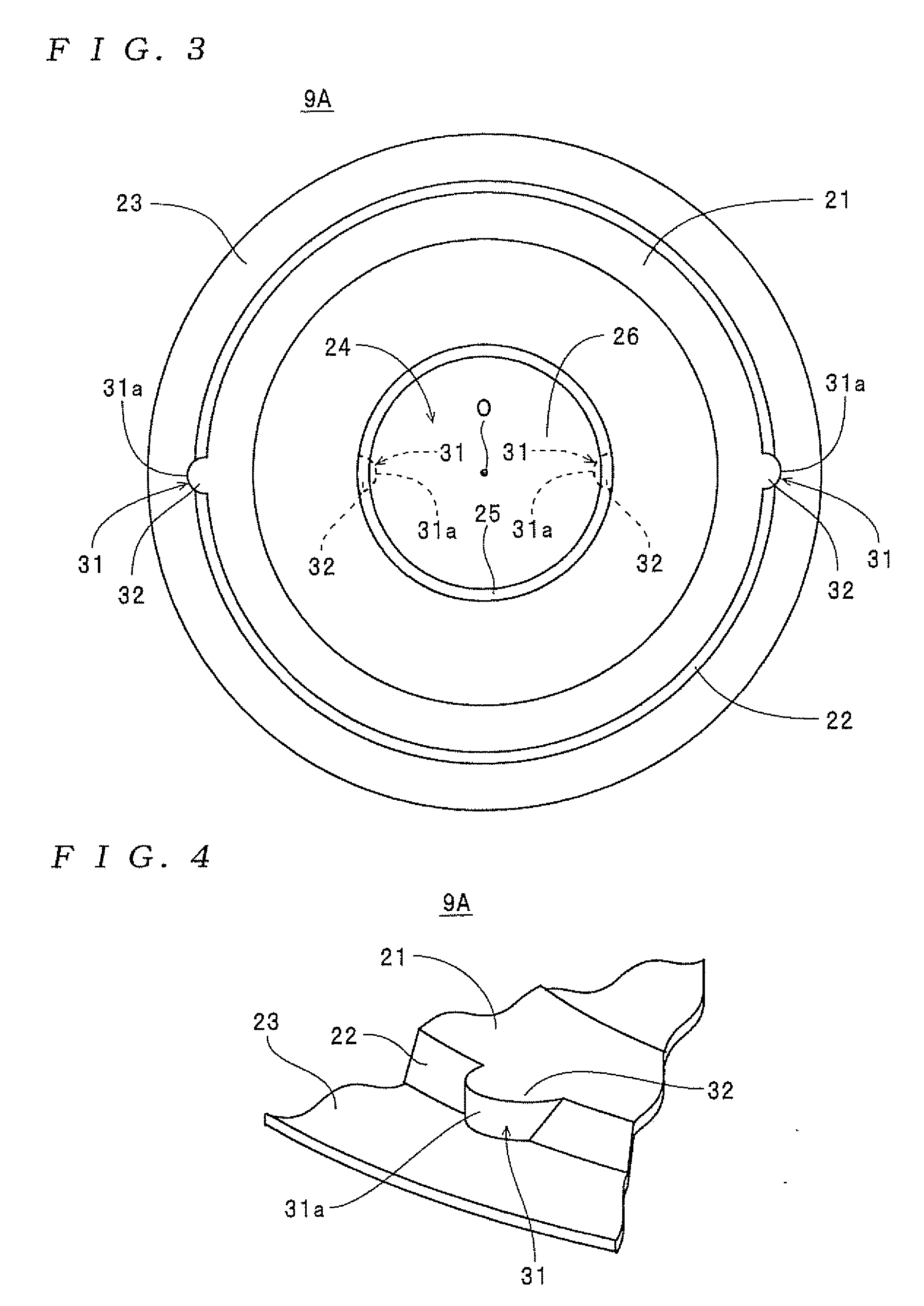
[0008] According to the clamping plate described above, by forming at least one of a convex that protrudes outward in a radial direction of the main plate and a concave that is depressed inward in the radial direction in the outer wall, when a convex is formed in the outer wall, even if the main plate of a given clamping plate is inserted inside the outer wall of another clamping plate (on the rear of the main plate) so as to jam the clamping plates together, an upper surface of the convex of the given clamping-plate will contact one end of the outer wall of the other clamping plate (“an outer end in the direction of
insertion”, here an opposite end of the outer wall to the main plate), thereby preventing
insertion. Similarly, when a concave is formed in the outer wall, even if the main plate of a given clamping plate is inserted inside the outer wall of another clamping plate (from the rear of the main plate) so as to jam the clamping plates together, one end of the outer wall of the given clamping plate (“an inner end in the direction of
insertion”, here the main plate-end of the outer wall) will contact a rear surface of a base surface of the concave of the other clamping plate, thereby preventing insertion. This means that by forming at least one of a convex and a concave on the outer wall, even if a large number of clamping plates are stored as
assembly components in a component storage box or the like, it is possible to keep the clamping plates apart without the clamping plates becoming jammed together. Accordingly, a complex separating operation is unnecessary and
grinding or attachment to a cartridge case or disk-shaped recording medium can start immediately for the clamping plates. As a result, it is possible to reduce the manufacturing cost of a disc cartridge (information recording medium).
[0009] Here, the clamping plate may be formed so that the outer wall is formed in a taper so that the
diameter thereof increases as the distance from the main plate increases, and the convex is formed so that a protruding end part thereof protrudes further outward than a largest
diameter part of the outer wall. With this construction, the convex will reliably contact the largest
diameter part of the outer wall, and therefore it is possible to reliably keep respective clamping plates apart.
[0011] According to the clamping plate described above, by forming at least one of a convex that protrudes inward in a radial direction of the main plate and a concave that is depressed outward in the radial direction in the inner wall, when a convex is formed in the inner wall, even if the main plate of a given clamping plate is inserted inside the outer wall of another clamping plate (on the rear of the main plate) so as to jam the clamping plates together, an upper surface of the convex of the given clamping plate will contact one end of the inner wall of the other clamping plate (“an outer end in the direction of insertion”, here a circular concave base portion-end of the inner wall), thereby preventing insertion. Similarly, when a concave is formed in the inner wall, even if the main plate of a given clamping plate is inserted inside the outer wall of another clamping plate (from the rear of the main plate) so as to jam the clamping plates together, one end of the inner wall of the given clamping plate (“an inner end in the direction of insertion”, here the main plate-end of the inner wall) will contact a rear surface of a base surface of the concave of the other clamping plate, thereby preventing insertion. This means that even if a large number of clamping plates are stored as
assembly components in a component storage box or the like, it is possible to keep the clamping plates apart without the clamping plates becoming jammed together. Accordingly, a complex separating operation is unnecessary and
grinding or attachment to a cartridge case or disk-shaped recording medium can start immediately for the clamping plates. As a result, it is possible to reduce the manufacturing cost of a disc cartridge (information recording medium).
[0012] Here, the clamping plate may be formed so that the inner wall is formed in a taper so that the diameter thereof decreases as the distance from the main plate increases, and the convex is formed so that a protruding end part thereof protrudes further inward than a smallest diameter part of the inner wall. With this construction, the convex will reliably contact the smallest diameter part of the inner wall, and therefore it is possible to reliably keep respective clamping plates apart.

