Integrated light-emitting device

Inactive Publication Date: 2006-11-23
YANG PI FU
View PDF3 Cites 53 Cited by
  • Summary
  • Abstract
  • Description
  • Claims
  • Application Information

AI Technical Summary

Benefits of technology

[0013] Therefore, the object of the present invention is to provide an integrated light-emitting device, wh

Problems solved by technology

(1) The aforesaid method for making the conventional light-emitting device involves lengthy and complex manufacturing steps, such as drilling, milling and polishing.
With the complex processing steps, it is difficult to control the depth, dimension, angle and position of the recess 110 precisely, which in turn leads to higher yield loss of end products.
Additionally, the drilling, milling and polishing steps are tedious an

Method used


Image

  • Integrated light-emitting device
  • Integrated light-emitting device
  • Integrated light-emitting device

Examples


Example

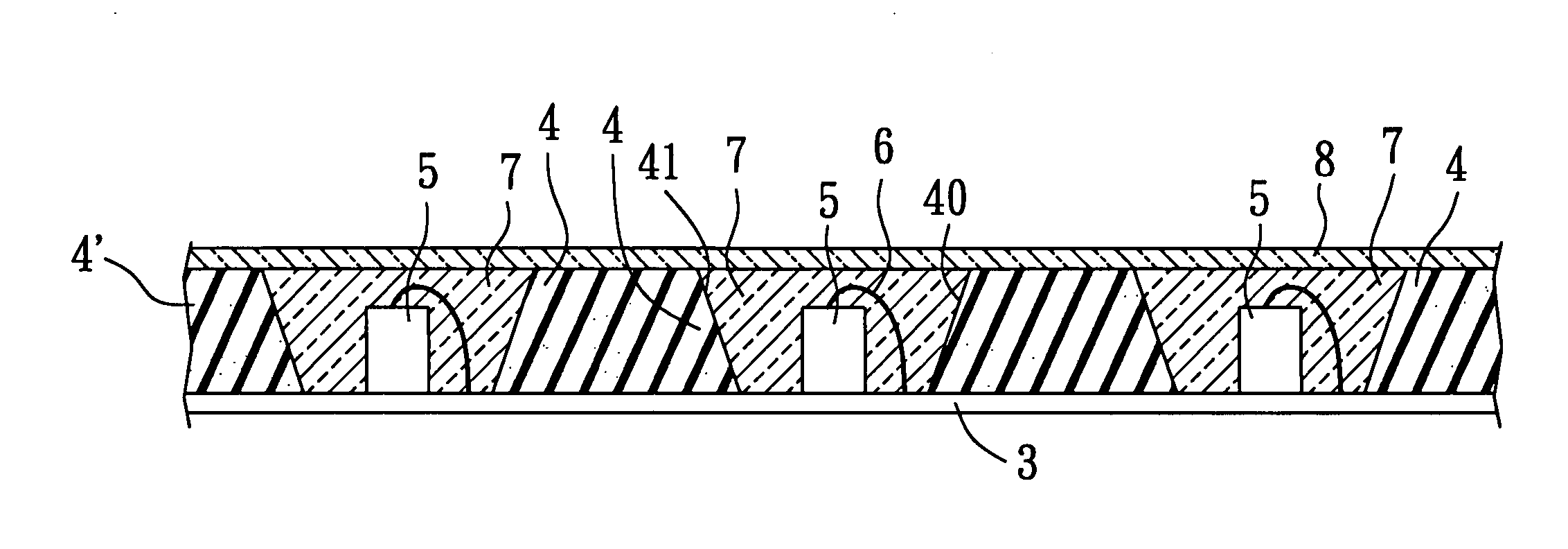
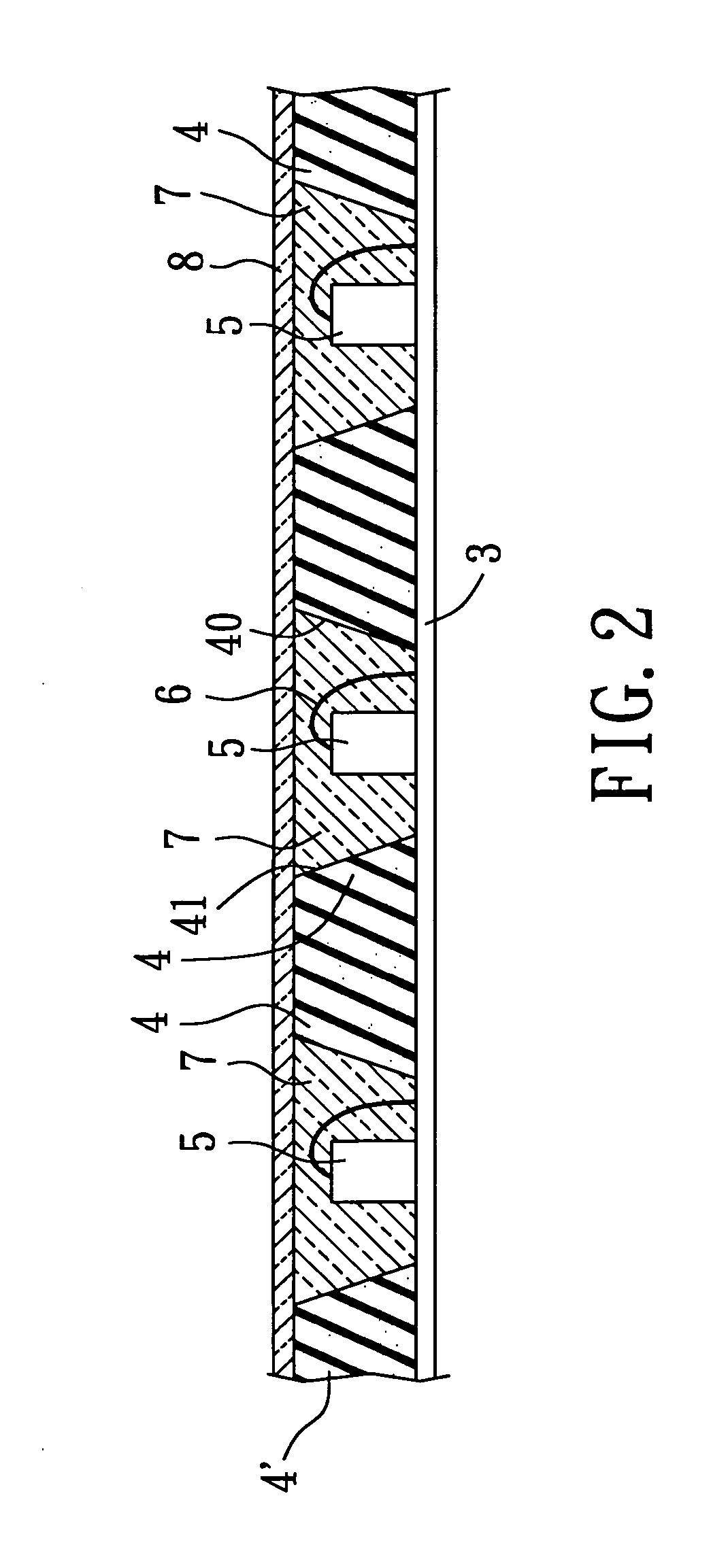
[0021] Referring to FIG. 2, the preferred embodiment of an integrated light-emitting device according to this invention is shown to include a substrate 3, a reflecting layer 4′, a plurality of light-generating sources 5, a plurality of conductive wires 6, an encapsulating layer 7, and a brightness enhancement prism film 8. The reflecting layer 4′ is molded over the substrate 3, and contains a plurality of reflector cups 4 each of which defines a cup-shaped recess 40. Each of the reflector cups 4 has a reflective surface 41 in the cup-shaped recess 40. Each of the light-generating sources 5 is mounted on the substrate 3 within the cup-shaped recess 40 of a corresponding one of the reflector cups 4. Each of the conductive wires 6 connects electrically a corresponding one of the light-generating sources 5 to the substrate 3. The encapsulating layer 7 is molded over the cup-shaped recess 40 of each of the reflector cups 4 and the light-generating sources 5. The brightness enhancement pr...


PUM


Abstract

An integrated light-emitting device includes a substrate, a reflecting layer containing at least one reflector cup molded over the substrate to define a cup-shaped recess and having a reflective surface in the cup-shaped recess, a light-generating source mounted on the substrate within the cup-shaped recess, an encapsulating layer molded over the cup-shaped recess and the light-generating source, and a brightness enhancement prism film attached onto the encapsulating layer and patterned to form a plurality of prism structures.

Description

CROSS-REFERENCE TO RELATED APPLICATION [0001] This application claims priority of Taiwanese Application No. 094116316, filed on May 19, 2005. BACKGROUND OF THE INVENTION [0002] 1. Field of the Invention [0003] The invention relates to a light-emitting device, more particularly to an integrated light-emitting device. [0004] 2. Description of the Related Art [0005] Light emitting diodes (LEDs) are broadly utilized in various applications, such as displays, light-emitting devices, and the like, since they have advantages, such as low driving voltage and high light efficiency. [0006] Referring to FIG. 1, a conventional light-emitting device including an LED die 12 as a light generating source is usually produced by drilling a printed circuit board 11 to form a recess 110 having a cup-shaped wall, plating a reflective metal substance on the cup-shaped wall of the recess 110 to form a reflective surface 10 on the cup-shaped wall of the recess 110, attaching the LED die 12 within the reces...

Claims


Application Information

Patent Timeline
IPC IPC(8): H01L29/24H01L33/50H01L33/60H01L33/62
CPCH01L33/58H01L2224/48091H01L2924/00014
Inventor YANG, PI-FU
Owner YANG PI FU
Why Eureka
Try Eureka