Grain moisture sensor

a technology of grain moisture sensor and sensor, which is applied in the direction of measuring devices, fertiliser distributors, instruments, etc., can solve the problems of increasing the difficulty of manufacturing and maintenance of this device, the difficulty of determining the exact point at which the reading is taken, and the difficulty of acquiring the device for either manufacture or repair, so as to facilitate the detection of the desired zero point, reduce the complexity, and the effect of reducing the complexity

Inactive Publication Date: 2006-11-23
FRASER WILLIAM JOHN
View PDF14 Cites 6 Cited by
  • Summary
  • Abstract
  • Description
  • Claims
  • Application Information

AI Technical Summary

Benefits of technology

[0059] Because the frequency difference passes from positive to negative, rather than dipping to a minimum and rising again, it is much easier to detect the desired zero point. This ability is further enhanced with the digital display which provides positive and negative non-zero readings and an unequivocal zero re

Problems solved by technology

Unfortunately, the manufacture and maintenance of this device has become difficult due to the age of the technology.
Hence, it is becoming increasingly more difficult to acquire them for either manufacture or repair.
In addition to the concerns ove

Method used


Image

  • Grain moisture sensor
  • Grain moisture sensor
  • Grain moisture sensor

Examples


Embodiment Construction

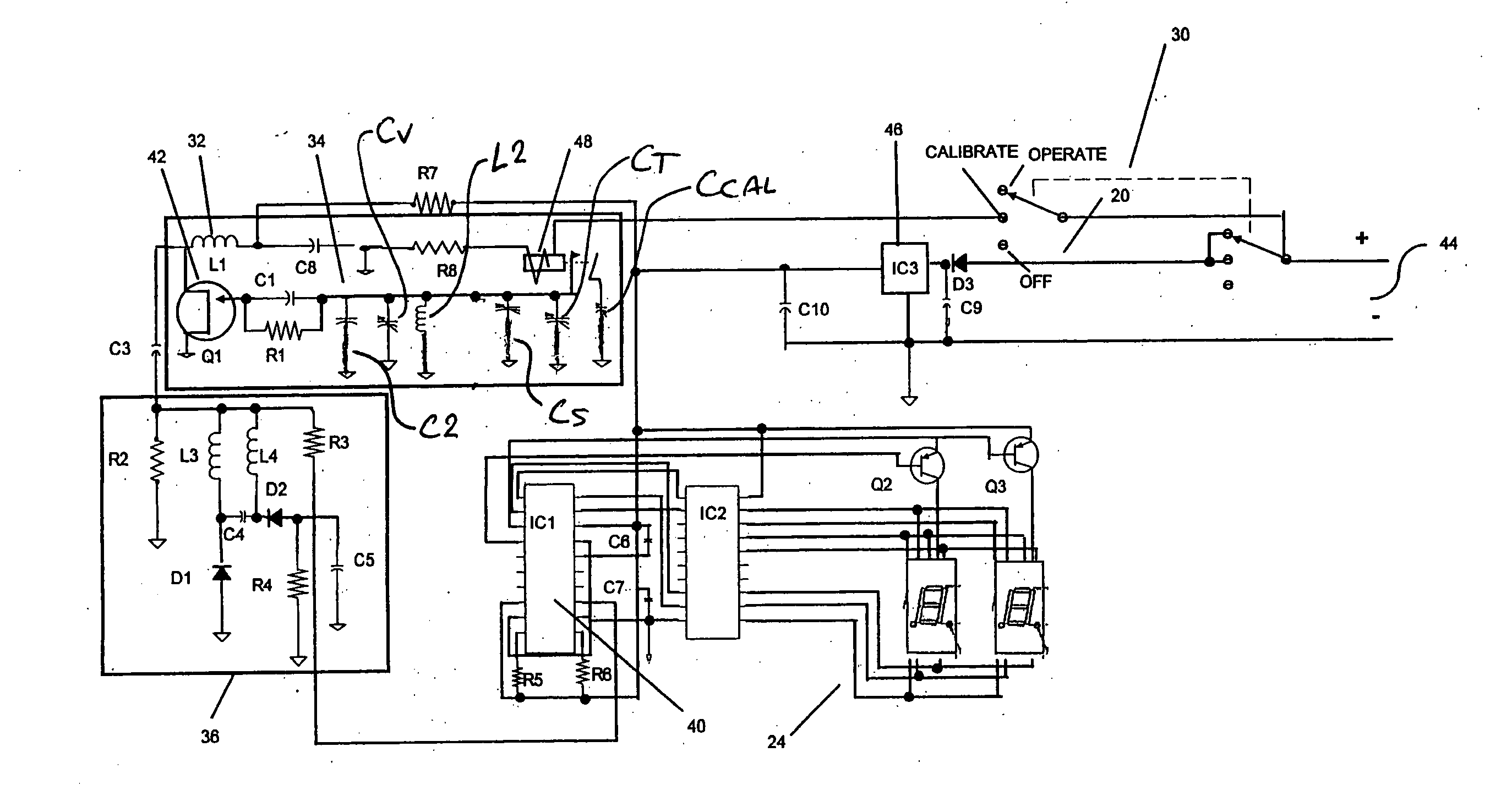
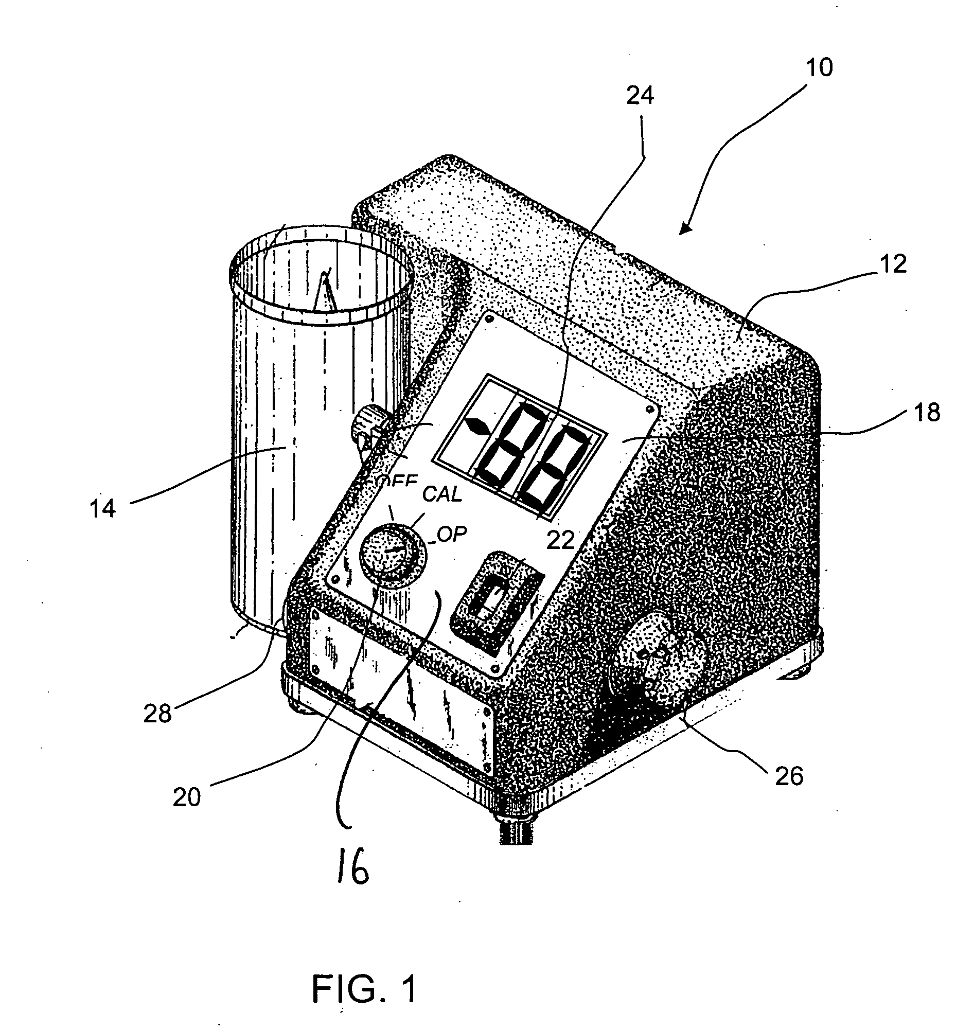
[0067] Referring to the accompanying drawings, there is illustrated a moisture tester 10 having a housing 12 and a test cell 14 for containing a sample of material to be tested. The configuration of the test cell and its mounting and connection to the housing are as described in CA 510,356. The front face 16 of the housing carries a panel 18 on which is mounted a multi-position switch 20 with “off”, “calibrate” and “operate” positions. The panel 18 also carries an indicator dial 22 for a standardized variable capacitor Cs (FIG. 3) and a two digit digital display 24. On one side of the housing is a knob 26 for adjusting the standardized variable capacitor with which the dial 22 is associated, while a trim knob 28 is mounted on the opposite side of the housing for adjusting a trimming capacitor. These components have equivalents in the device described in CA 510356, to which the reader is referred.

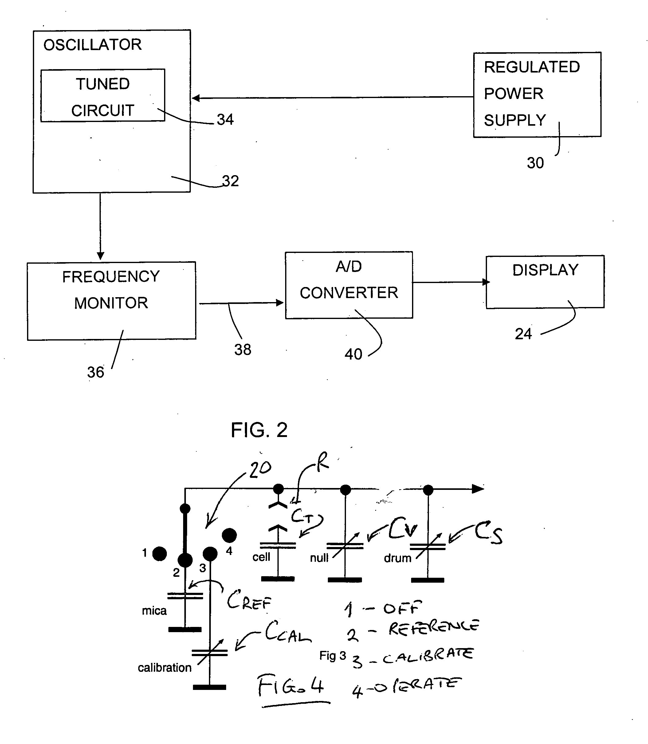
[0068] Turning to FIG. 2, the device according to the present invention has a regulated...


PUM


Abstract

A meter is disclosed for measuring the dielectric constant of a particulate material, particularly grain, as a function of its moisture content. The meter includes a test cell for containing a sample of the particulate material to be tested. A single oscillator includes a variable frequency tuned circuit for varying the frequency of the single oscillator output. The tuned circuit includes a test cell capacitor using a sample of material to be tested as a dielectric, a calibrated variable standard capacitor and a variable trimming capacitor. An indicator is coupled to the calibrated variable standard capacitor to display a value representing the capacitance setting of the calibrated variable standard capacitor. A frequency monitor compares the output frequency of the oscillator with a selected frequency and a null display displays the difference between the output frequency of the oscillator and the selected frequency. In the invention, the frequency monitor generates DC outputs of opposite polarity according to whether the output frequency of the oscillator is greater than or less than the selected frequency and the null display is a digital display, displaying the frequency difference as zero when the output frequency of the oscillator equals the selected frequency, as a positive value when the output frequency of the oscillator is greater than the predetermined frequency and as a negative value when the output frequency of the oscillator is less than the predetermined frequency.

Description

[0001] This application is a continuation-in-part application from application Ser. No. 10 / 853,118 filed May 26, 2004 and now abandoned. [0002] This invention relates to an improved device for determining certain properties of particulate materials, most particularly the moisture content of grains and similar materials.BACKGROUND OF THE INVENTION [0003] The moisture content of grains and like material has a significant impact on the market value of the grain. If grains have too high of moisture content they will sell for less than those in an appropriate moisture range. Therefore, an accurate and precise means of testing moisture content in grain will help farmers monitor their crops. With the aid of monitoring, farmers may dry their grain until the preferred moisture content is achieved. This will minimize energy input while increasing grain value. [0004] There are many grain moisture sensing devices found in the patent literature. Greenwood et al. Canadian patent 510356, issued Fe...

Claims


Application Information

Patent Timeline
IPC IPC(8): G01R27/26A01C15/02
CPCA01C15/02
Inventor FRASER, WILLIAM D.
Owner FRASER WILLIAM JOHN
Why Eureka
Try Eureka