[0012] It is another object of the invention to provide an
instrumentation amplifier which has a wide common mode input
voltage range and which avoids producing abrupt changes and / or inaccuracies in its output
signal if the common mode input voltage applied to the instrumentation amplifier undergoes a transition from a positive to a negative value or vice versa.
[0013] Briefly described, and in accordance with one embodiment, the present invention provides an amplifier circuit including first (7A) and second (7B) operational amplifiers connected in a generally parallel configuration, each with inputs coupled through the same pair of matched input resistors which receive a differential input signal that may have both a positive and negative common mode range. An offset adjustment amplifier (17) receives a differential
error signal representative of the difference between offset voltages of the first and second operational amplifiers and generates offset adjustment signals that are applied to the input stage of at least one of the first and second operational amplifiers to adjust their respective offset voltages so as to equalize them. With the offset voltages equalized, the first and second operational amplifiers operate seamlessly as a common mode component of the differential input signal undergoes a transition from its positive to its negative range, so as to avoid inaccuracies and abrupt changes in an output voltage during the transition , the output voltage being produced by the first and second operational amplifiers.
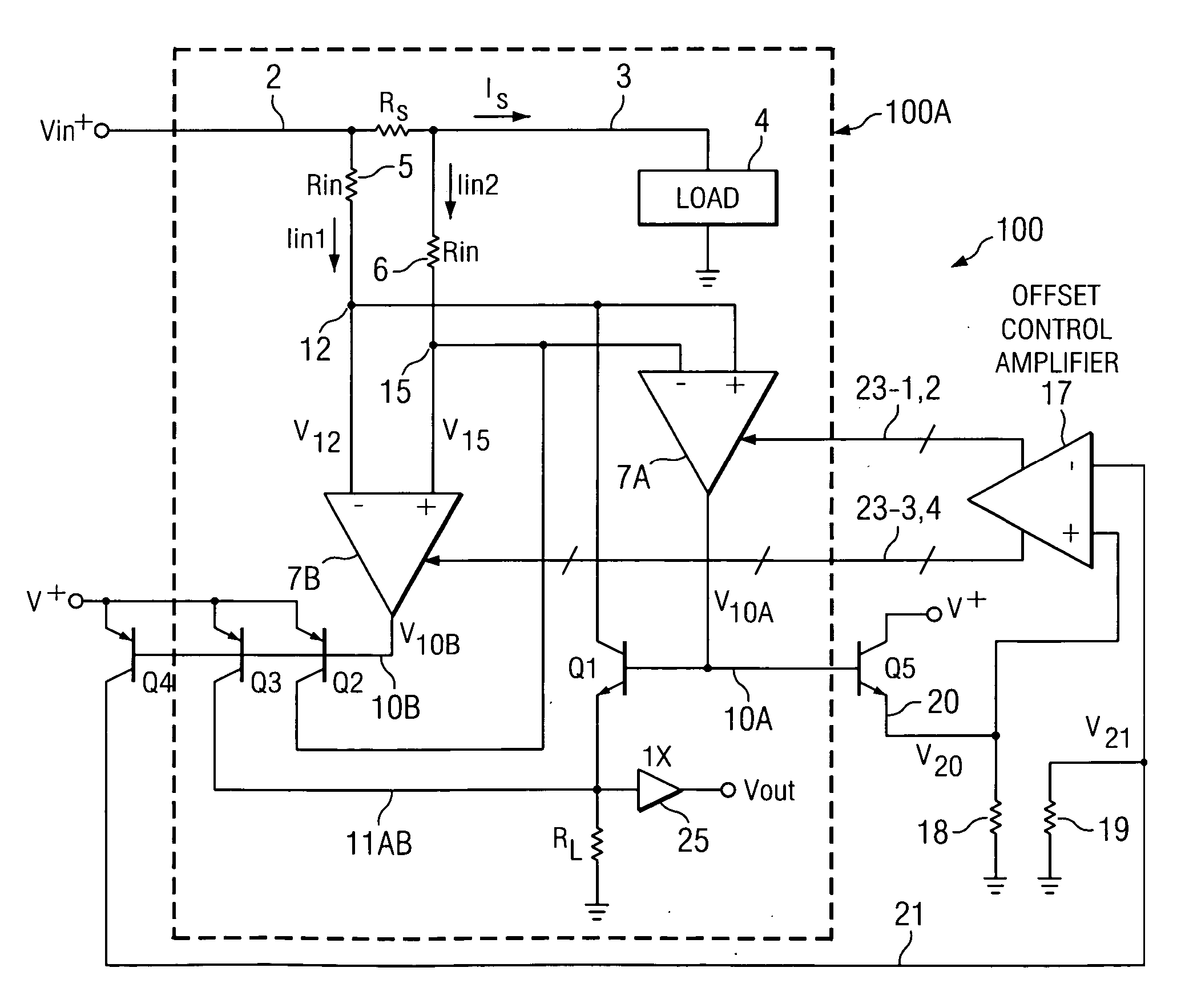
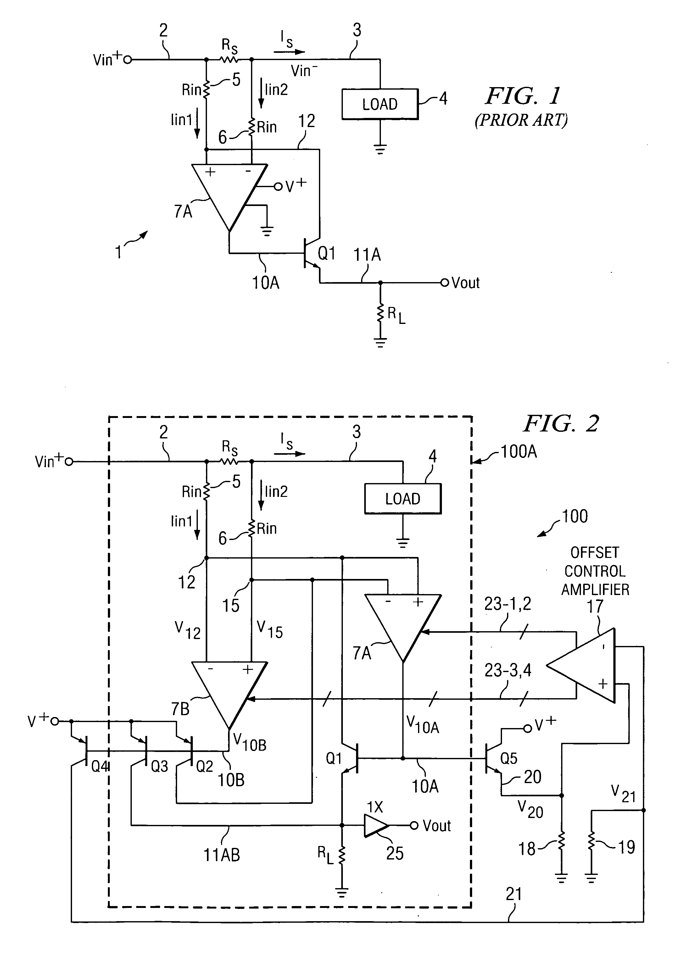
[0014] In the described embodiments, an instrumentation amplifier circuit (100) including a first
operational amplifier (7A) having a non-inverting input coupled to a first terminal of a first input resistor (5), an inverting input coupled to a first terminal of a second input resistor (6), and an output (10A) coupled to a control
electrode (e.g., base) of a first output
transistor (Q1). The first output
transistor (Q1) has a first
electrode (e.g., emitter) coupled to a first output conductor (11AB) and a first terminal of a load resistor (RL) and a second
electrode (e.g., collector) coupled to the first terminal of the first resistor (5), the load resistor (RL) having a second terminal coupled to a first reference voltage (GND). A differential input voltage is applied between a second terminal (2) of the first input resistor (5) and a second terminal (3) of the second input resistor (6). The differential input voltage has a common mode component that extends through both a positive and
negative voltage range. The instrumentation amplifier also includes a second
operational amplifier (7B) having an inverting input coupled to the first terminal of the first resistor (5), a non-inverting input coupled to the first terminal of the second resistor (6), and an output (10B) coupled to a control electrode (e.g., base) of a second output
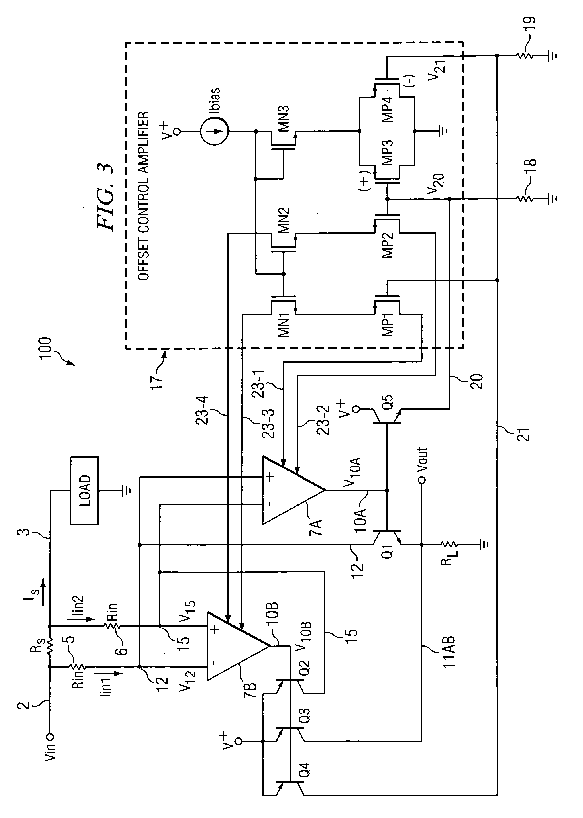
transistor (Q2) and a control electrode (e.g., base) of a level translation transistor (Q3), the second output transistor (Q2) having a first electrode (e.g., emitter) coupled to a second reference voltage (V+) and a second electrode (e.g., collector) coupled to the first terminal of the second resistor (6), the level translation transistor (Q3) having a first electrode (e.g., emitter) coupled to the second reference voltage (V+) and a second electrode (e.g., collector) coupled to the first output conductor (11AB). The instrumentation amplifier further includes offset adjustment circuitry including an offset control amplifier (17) having a non-inverting input and an inverting input for receiving a differential
error signal representative of a difference between an offset voltage of the first operational amplifier (7A) and an offset voltage of the second operational amplifier (7B). A first transistor (Q5) has a control electrode (e.g., base) coupled to the output (10A) of the first operational amplifier (7A), a first electrode (e.g., emitter) coupled to the non-inverting input of the offset control amplifier (17), and a second electrode (collector) coupled to the second reference voltage (V+). A second transistor (Q4) has a control electrode (e.g., base) coupled to the output (10B) of the second operational amplifier (7B), a first electrode (e.g., emitter) coupled to the second reference voltage (V+), and a second electrode (collector) coupled to the inverting input of the offset control amplifier (17). The offset control amplifier (17) includes a first offset adjustment output (23-1,2) operatively coupled to adjust an offset voltage of one of the first (7A) and (7A) operational amplifiers. The offset adjustment circuitry operates so as to minimize a difference between offset voltages of the first (7A) and second (7B) operational amplifiers.
[0018] In a described embodiment, the offset control amplifier (17) is operatively coupled to the first (7A) and second (7B) operational amplifiers so as to cause one of them to dominate the other within a transition region between positive and negative values of a common mode component of the differential input voltage in order to prevent abrupt and / or indeterminate values of an output voltage produced on the first output conductor (11AB) within the transition region.

