
Signal processing device

Inactive Publication Date: 2017-10-19
KYB CORP
View PDF0 Cites 0 Cited by
  • Summary
  • Abstract
  • Description
  • Claims
  • Application Information

AI Technical Summary

Benefits of technology

The patent is about a device that can gradually change the rate at which it controls an output signal, to avoid sudden changes during switching between control commands. The device uses a complex process to calculate and blend in the control commands, resulting in a smooth transition between them. The technical effect of this invention is to reduce the suddenness of output signal changes.

Problems solved by technology

However, simply switching between the skyhook control current and the roll / pitch control current can cause a sudden change in the rate of change of a control command output before the switching and after the switching.
However, recent dampers with high damping force generation responsivity using magnetorheological fluids, electrological fluids, and the like can suddenly change in damping force due to sudden changes in the rates of change of control commands, deteriorating rides in vehicles.
However, this way of switching by fading in and fading out control commands cannot avoid a sudden change in the damping force of a damper with high damping force generation responsivity because the rate of change of a control command synthesized at the start and at the end of fade-in and fade-out changes suddenly.
Other than damper control, a sudden change in the rate of change of a signal at the time of switching between two signals adversely affects the control of apparatuses with high responsivity to control commands, and the like.

Method used


Image

  • Signal processing device
  • Signal processing device
  • Signal processing device

Examples


Embodiment Construction

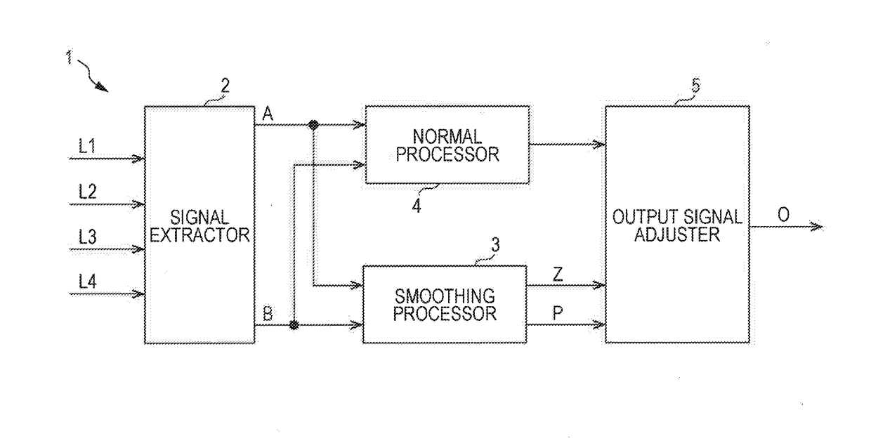
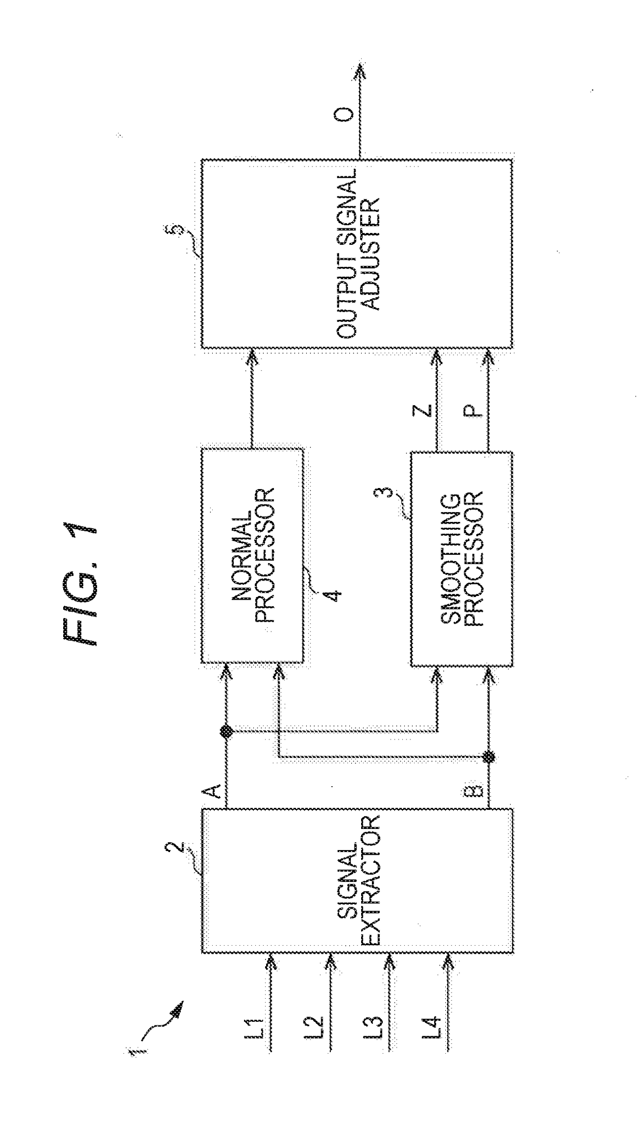
[0039]Hereinafter, the present invention will be described, based on embodiments illustrated in the drawings. As illustrated in FIG. 1, a signal processing device 1 in a first embodiment includes a signal extractor 2 that extracts two signals A and B from a plurality of signals L1, L2, L3, and L4, and a smoothing processor 3 that generates a smoothing signal P based on the deviation ε between the two signals A and B. The signal processing device 1 generates the smoothing signal P that reduces a sudden change in the rate of change of a signal at the time of switching when a selected signal of the two signals A and B is switched.

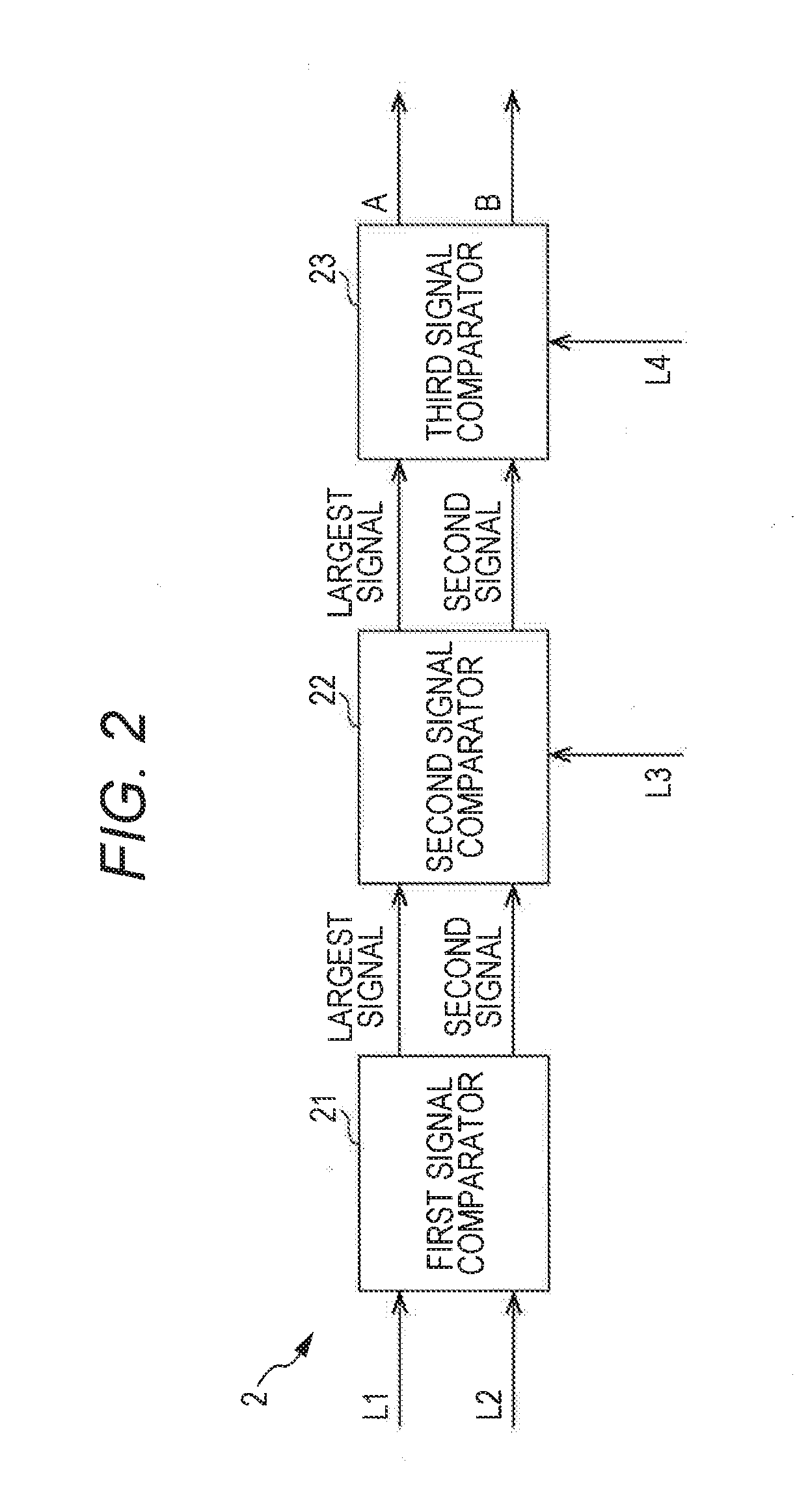
[0040]The signal processing device 1 in the first embodiment performs the so-called high select processing in this example. The signal extractor 2 extracts a signal having the largest value and a signal having the second largest value as the two signals A and B from the plurality of signals L1, L2, L3, and L4.

[0041]As illustrated in FIG. 2, the signal extracto...


PUM


Abstract

An object is to provide a signal processing device capable of reducing a sudden change in the rate of change of an output signal at the time of switching between two signals. In the signal processing device, when a signal of a larger value is selected, a smoothing signal is generated based on the deviation between two signals such that the smoothing signal has a value larger than the values of the two signals between two points at which the smoothing signal intersects the two signals, or when a signal of a smaller value is selected, the smoothing signal is generated based on the deviation between two signals such that the smoothing signal has a value smaller than the values of the two signals between two points at which the smoothing signal intersects the two signals.

Description

TECHNICAL FIELD[0001]The present invention relates to a signal processing device.BACKGROUND ART[0002]Control used in damper control devices for controlling the damping force of dampers interposed between spring upper members and spring lower members of vehicles includes well-known skyhook control the object of which is to reduce vibrations of the spring upper members, focusing on vibrations of the spring upper members. In addition to the skyhook control, roll / pitch control for reducing rolling and pitching of the spring upper members is sometimes combined to control the damping force of dampers, as disclosed in JP 2006-44523 A, for example.[0003]This damper control device provides control commands to a damping force adjustment mechanism that changes damping force produced by a damper according to a supply current, to control the damping force. Specifically, the damper control device determines a skyhook control current as a control command to be provided to the damping force adjustm...

Claims


Application Information

Patent Timeline
IPC IPC(8): B60G17/018
CPCB60G2500/10B60G17/018G05B7/02B60G2800/012B60G2800/014B60G2800/702B60W50/06
Inventor KUBOTA, TOMOOOKUMURA, MASATOSHI
Owner KYB CORP
Learn More