Vehicle electrical system and methods

a technology of electrical system and vehicle, applied in the direction of machines/engines, transportation and packaging, engine starters, etc., can solve the problems of limited current carrying capacity, and reducing so as to prevent current flow, and reduce the possibility of isolation switch degradation

Active Publication Date: 2021-09-28
FORD GLOBAL TECH LLC
View PDF7 Cites 3 Cited by
  • Summary
  • Abstract
  • Description
  • Claims
  • Application Information

AI Technical Summary

Benefits of technology

[0002]A vehicle may include low voltage (e.g., 12 VDC) starter and a high voltage integrated starter / generator (ISG). In addition, the vehicle may include accessory electric loads that may be selectively electrically decoupled from the starter so that the accessory electric loads may not be exposed to low voltages that may result from supplying large amounts of electrical current to the starter during engine starting. An electric isolation switch may be selectively opened and closed to allow or prevent current flow between a primary electric energy storage device and an accessory electric energy storage device. In particular, the electric isolation switch may be opened to prevent current flow between the electric energy storage devices during engine cranking and starting. The electric isolation switch may be closed after engine cranking and starting so that both the primary and accessory electric energy storage devices may be charged via a belt integrated starter / generator (BISG), which may be a low voltage starter. However, the electric isolation switch may have limited current carrying capacity, and high electric current flow through the electric isolation switch may lead to degradation of the electric isolation switch. Therefore, it may be desirable to provide a way of reducing the possibility of high electric current flow through the electric isolation switch.
[0004]By reducing a voltage of a low voltage primary electric energy storage device, it may be possible to reduce electric current flow through an electric isolation switch that selectively couples and decouples the low voltage primary electric energy storage device from a low voltage accessory electric energy storage device. For example, if during engine cranking, the voltage of the low voltage accessory electric energy storage device is reduced by supplying electric power to ancillary vehicle electric power consumers, then a voltage of a low voltage primary electric energy storage device may be reduced so that current flow through the electric isolation switch may be reduced when the electric isolation switch is closed after engine cranking.
[0005]The present description may provide several advantages. In particular, the approach may reduce the possibility of isolation switch degradation. Further, the approach may increase a life span of an electric isolation switch. Further still, the approach may reduce abrupt changes in system voltage levels.

Problems solved by technology

However, the electric isolation switch may have limited current carrying capacity, and high electric current flow through the electric isolation switch may lead to degradation of the electric isolation switch.
In particular, the approach may reduce the possibility of isolation switch degradation.
Further, the approach may increase a life span of an electric isolation switch.

Method used


Image

  • Vehicle electrical system and methods
  • Vehicle electrical system and methods
  • Vehicle electrical system and methods

Examples


Embodiment Construction

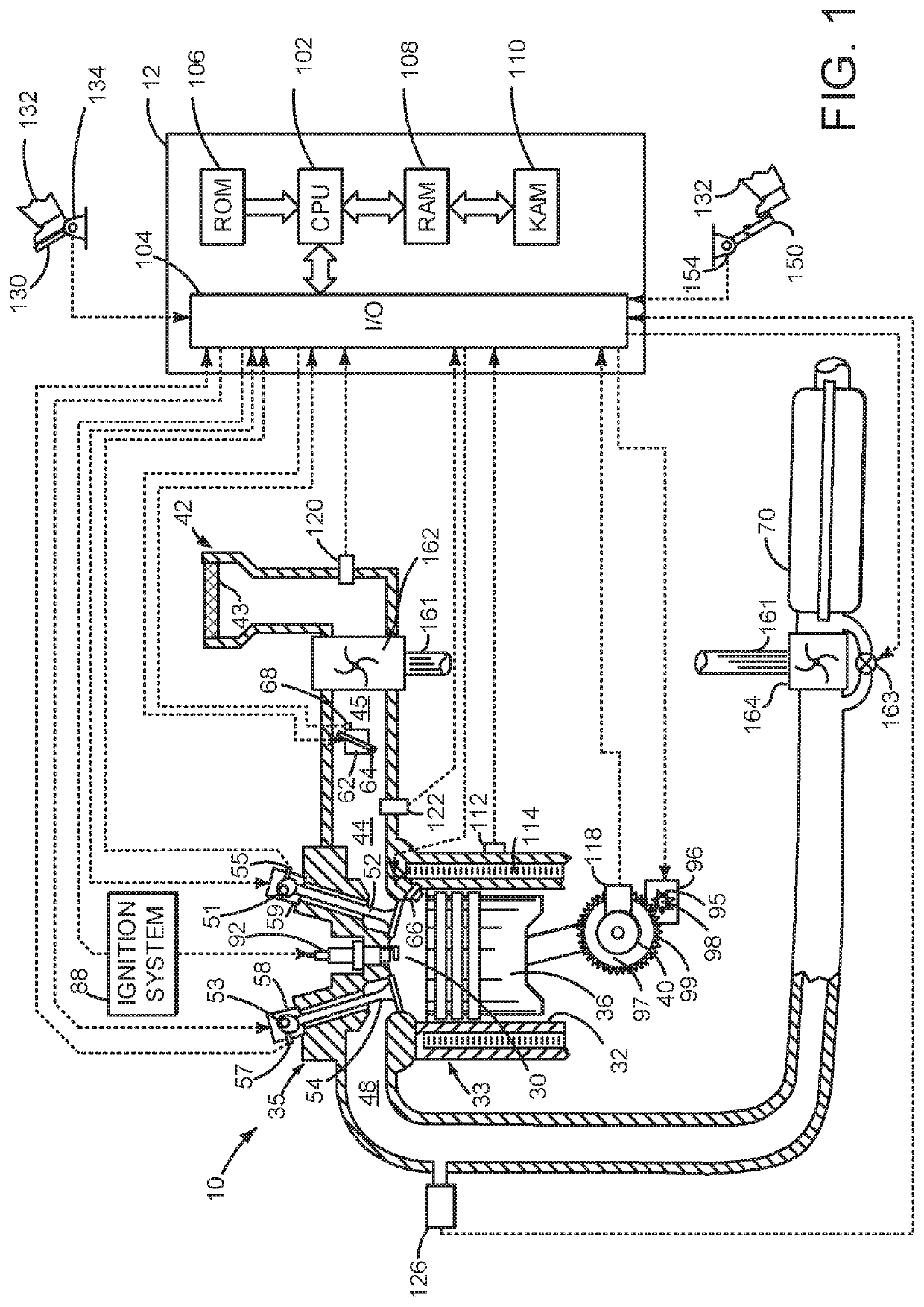
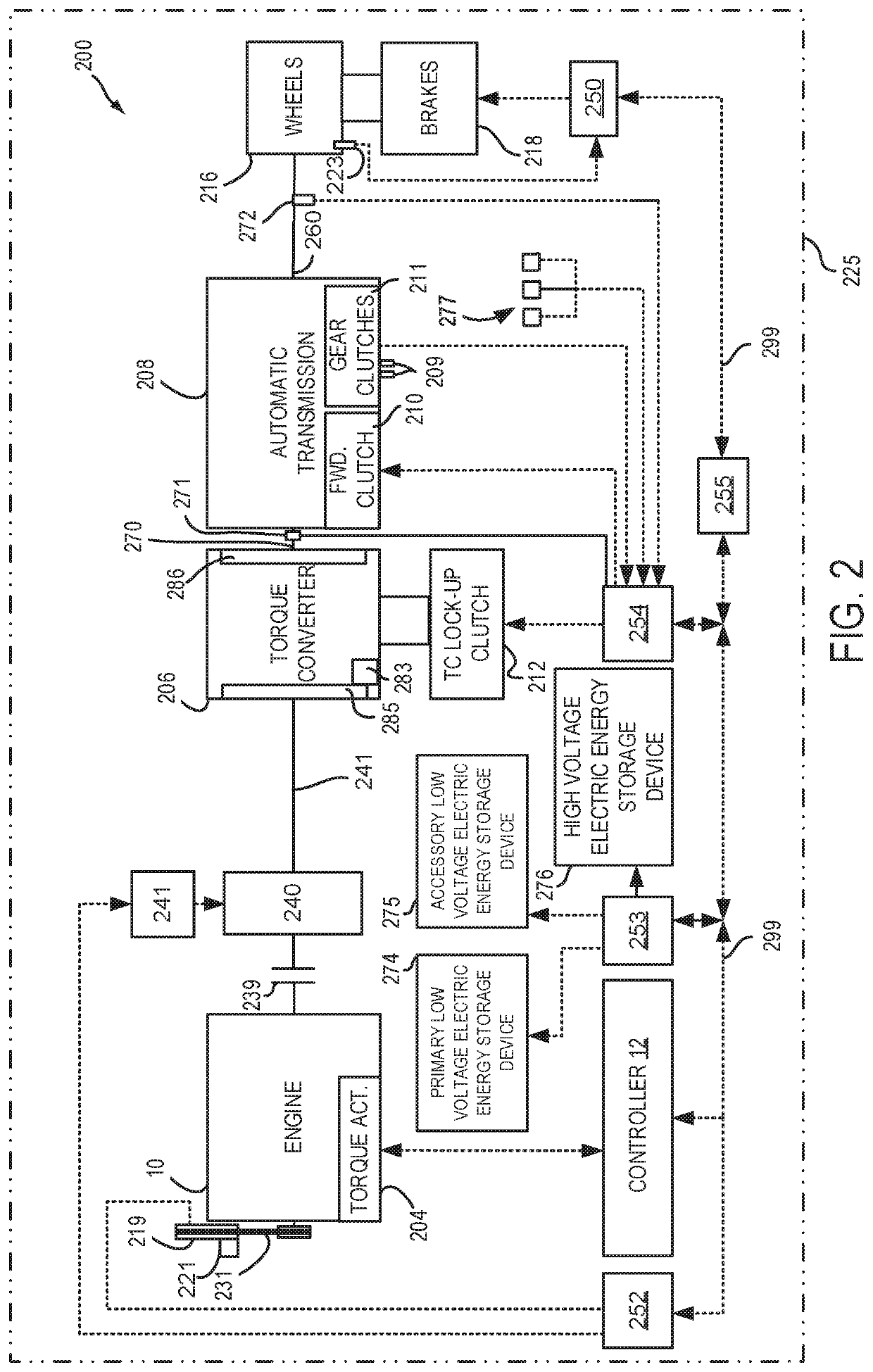
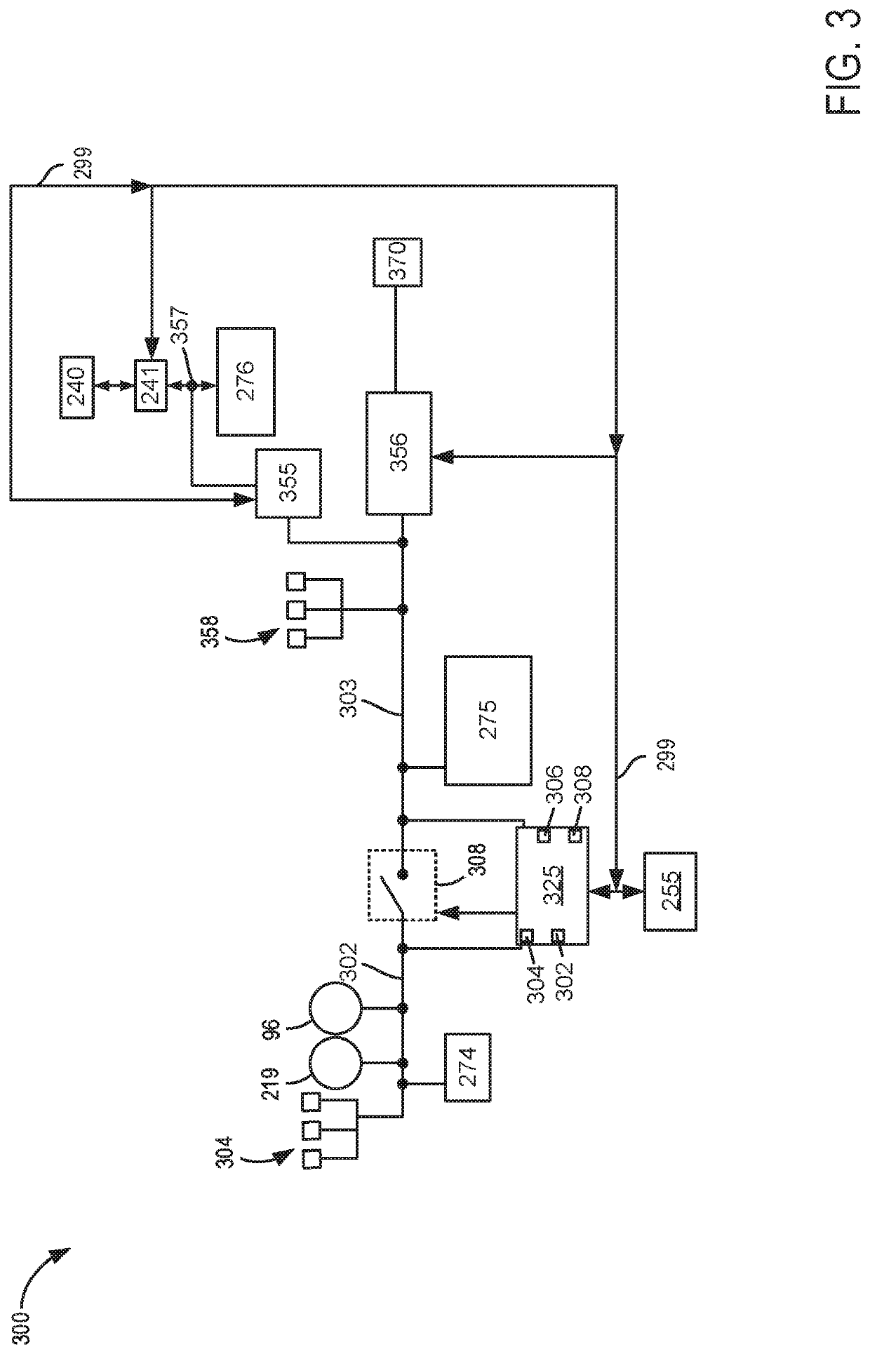
[0014]The present description is related to controlling electrical power delivered onboard and off-board of a vehicle that generates electrical power. The vehicle may generate electrical power via an internal combustion engine as shown in FIG. 1. The internal combustion engine may be included in a driveline or powertrain of a vehicle as shown in FIG. 2. The vehicle may include an electrical power distribution system as shown in FIG. 3. The vehicle electrical power distribution system may operate according to the sequence of FIG. 4. The method of FIGS. 5 and 6 may operate in cooperation with the system shown in FIGS. 1-3 to provide the sequences shown in FIG. 4.

[0015]Referring to FIG. 1, internal combustion engine 10, comprising a plurality of cylinders, one cylinder of which is shown in FIG. 1, is controlled by electronic engine controller 12. The controller 12 receives signals from the various sensors shown in FIGS. 1 and 2. In addition, controller 12 employs the actuators shown in...


PUM


Abstract

Systems and methods for supplying electrical power between two electric energy storage devices are disclosed. In one example, an electric isolation switch is held open after engine starting until a voltage of a first electric energy storage device and a voltage of a second electric energy storage device are within a threshold voltage of at least one predetermined voltage level.

Description

FIELD[0001]The present description relates to systems and methods for distributing electrical power in a vehicle. The system and methods may be suitable a vehicle that includes more than one electrical power distribution bus.BACKGROUND AND SUMMARY[0002]A vehicle may include low voltage (e.g., 12 VDC) starter and a high voltage integrated starter / generator (ISG). In addition, the vehicle may include accessory electric loads that may be selectively electrically decoupled from the starter so that the accessory electric loads may not be exposed to low voltages that may result from supplying large amounts of electrical current to the starter during engine starting. An electric isolation switch may be selectively opened and closed to allow or prevent current flow between a primary electric energy storage device and an accessory electric energy storage device. In particular, the electric isolation switch may be opened to prevent current flow between the electric energy storage devices duri...

Claims


Application Information

Patent Timeline
Patent Type & Authority Patents(United States)
IPC IPC(8): F02N11/08B60R16/033B60R16/023
CPCF02N11/087B60R16/0238B60R16/033F02N11/0866B60R16/03F02N11/0862B60R16/0315F02N11/006F02N11/04F02N2200/063F02N2300/2002H02J7/1423H02J7/342H02J2310/46
Inventor GIBSON, ALEXANDER O'CONNORLEW, DAVID
Owner FORD GLOBAL TECH LLC
Why Eureka
Try Eureka